
|
||
| Network Testing and Emulation Solutions |
|
|
||
| Network Testing and Emulation Solutions |
The LANforge-Attenuator is designed to add RF attenuation on 2.4Ghz and 5Ghz WiFi connections. It supports 3 attenuator modules, each capable of adding attenuation to one connection. The attenuation range is 0 to 95.5 dB (see notes on signal strength below). The attenuation may be controlled by knobs on the front of the system, and may also be adjusted programmatically over a USB-serial port. Currently, the serial-port option is only available on Linux. Each attenuaton module may be configured independently of the others.
The LANforge software suite can also control the attenuator through its GUI and/or CLI for integrated testing scenarios. This includes built-in scripting to automatically adjust attenuation over time.
The LANforge-Attenuator uses the ATS0760-95 modules from EUBUS. A summary of the technical specifications is below:
| Type: | ATS0760-95 |
| Impedance: | 50 Ω |
| Frequency Range: | 0.7 GHz – 6.0 GHz |
| Attenuation Range: | 0 – 95.5dB |
| Attenuation Steps: | 0.5 dB increments |
| Attenuation Accuracy: | 1-15db: ±1dB, 16-95.5 dB: ±1.5dB or 4% ref. to Ins. Loss |
| Insertion Loss: | 8dB nominal, 10dB max |
| max. VSWR: | 2:1 |
| Maximum Input Power: | + 20 dBm |
| Operating Temperature: | 0°C to +70°C |
The LANforge-Attenuator contains 3 of these modules, for a total of 6 RP-SMA connectors on the front panel. Each pair of connectors provides one attenuation path. A micro-controller provides a control interface over a USB plug that appears as a USB-Serial adapter to the operating system. The attenuator does not require an external computer to function: It can be manually adjusted with two knobs, and has a small LCD screen to provide information to the user.
The top knob adjusts the LCD menu items. The first menu shows information. The second is to adjust all attenuator modules in lock-step. The next three or four menus (depending on if it is a three or four module attenuator) are for adjusting individual attenuator modules. The Debug and Test Cables menus can be ignored as they are specifically for Candela engineers. The Color menu is for changing the display color (using the bottom knob).
The bottom knob adjusts the attenuation when the selected menu is All or individual attenuator modules. Pressing the knob down activates a button that toggles between each click adjusting by 5dBm or by 0.5dBm. Enabling the x5 mode enables quick adjustments over larger ranges, and the 0.5 mode allows fine tuning. When the selected menu is Color, the bottom knob changes the display color. Pressing the knob down saves the selected color and current attenuation values as the default setting.
The system may be powered off of a 500ma USB plug, but many computers only provide 100ma USB plugs, so it is suggested that the external DC power-brick (9v 1-Amp) be used at all times.
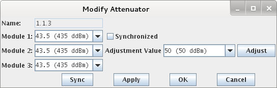
The LANforge software can manage the attenuator over the USB-Serial interface. It can be scripted in the 2544 and Hunt scripts in the LANforgeGUI. The LANforge CLI can also control one or more attenuators. Here is a screen-shot of the Attenuator control screen in the LANforge-GUI:
Users may also prefer to directly interface with the attenuator over the USB-Serial interface using minicom or some other serial-console application. The serial port will be named something like: /dev/ttyACM0, and the settings are: 115200 8N1. The LANforge-Attenuator provides a text-based interface, and supports these commands:
When testing, first connect attenuator 1 header to attenuator 4, press the bottom button to start the test. Each time you click it, a different header will be tested. So, when testing attenuator 3 header, expect 1 and 2 to fail, but 3 should pass. Attenuator 4 header is tested indirectly when testing any of the others.
The micro-controller in the LANforge Attenuator is configured to reset itself each time a new serial connection is made to the Attenuator. It only takes a second or two to boot, but this could cause interruption of testing if your application often opens and closes the serial connection. If you are controlling the attenuator over the serial connection, it is suggested that you program it in such a way that the serial connection remains up for the duration of the test. Please contact support if you have any questions on this.
The LANforge Attenuator has been designed with RF Isolation and accuracy in mind, but in testing with the LANforge CT520 WiFire traffic generator systems, we still see a bit of signal leakage even when attenuation is set to 95.5. We suspect that the CT520 systems leak a bit of signal out of their NICs and communicate directly, bypassing the attenuator.
The LANforge attenuator comes with 6 cables to connect the attenuator to systems under test. These cables use LMR-195 cable which also has isolation of > 90 dB. If you use your own cables, be sure they are of high quality for optimal performance. Our testing indicates that even these double-shielded LMR-195 cables may be leaking more that we hoped, so we will continue to investigate different cable types.
Our primary test setup is one 3-antenna AP connected to another 3-antenna Station system (3x3 MIMO Atheros/Qualcom radio). The AP and Station system are about 3 feet apart, and the attenuator system sits between them. The maximum attenuation gives a signal level of about -84 dB, and noise floor of about -92. This is right at the cut-off point for the AP and Station to communicate and they may loose association from time to time. Here is a graph of signal level v/s attenuation settings for this configuration. In this case, the signal went to about -86 and then lost connection (and so reported signal as 0).
The graph below shows the attenuation v/s rx-rate. The connection was lost at max attenuation and reported a zero signal. That makes the right-hand side of the graph a bit weird.
The LANforge-Attenuator uses an Arduino-Mega as the controller. The firmware is stored on flash in the controller and may be updated using the 'avrdude' program on a Linux machine. The firmware can be downloaded from the Downloads page. It will be named something like: attenuator-1.0.hex.
To upgrade, do the following steps. Do the console commands as the root user.
cd /home/lanforge; ./serverctl.bash stop
[root@lec2010-ath9k-1 lanforge]# tail -10 /var/log/messages
Oct 19 11:25:17 localhost dhclient[25360]: DHCPRELEASE on rddVR15 to 99.88.77.2 port 67
Oct 19 11:25:34 localhost kernel: [1276937.250169] usb 2-2: >USB disconnect, device number 23
Oct 19 11:25:39 localhost kernel: [1276941.370134] usb 2-2: >new full-speed USB device number 24 using uhci_hcd
Oct 19 11:25:39 localhost kernel: [1276941.571176] usb 2-2: >New USB device found, idVendor=2341, idProduct=0042
Oct 19 11:25:39 localhost kernel: [1276941.584803] usb 2-2: >New USB device strings: Mfr=1, Product=2, SerialNumber=220
Oct 19 11:25:39 localhost kernel: [1276941.599345] usb 2-2: >Manufacturer: Arduino (www.arduino.cc)
Oct 19 11:25:39 localhost kernel: [1276941.608628] usb 2-2: >SerialNumber: 74934303030351118071
Oct 19 11:25:39 localhost kernel: [1276941.620586] cdc_acm 2-2:1.0: >ttyACM0: USB ACM device
Oct 19 11:25:39 localhost mtp-probe: checking bus 2, device 24: "/sys/devices/pci0000:00/0000:00:1d.0/usb2/2-2"
Oct 19 11:25:39 localhost mtp-probe: bus: 2, device: 24 was not an MTP device
In this case, it is using /dev/ttyACM0
avrdude -patmega2560 -cstk500v2 -P/dev/ttyACM0 -b115200 -D -Uflash:w:attenuator-1.0.hex:i
The Latest drivers for arduino boards exist in the Arduino IDE package available
at the Arduino Software page.
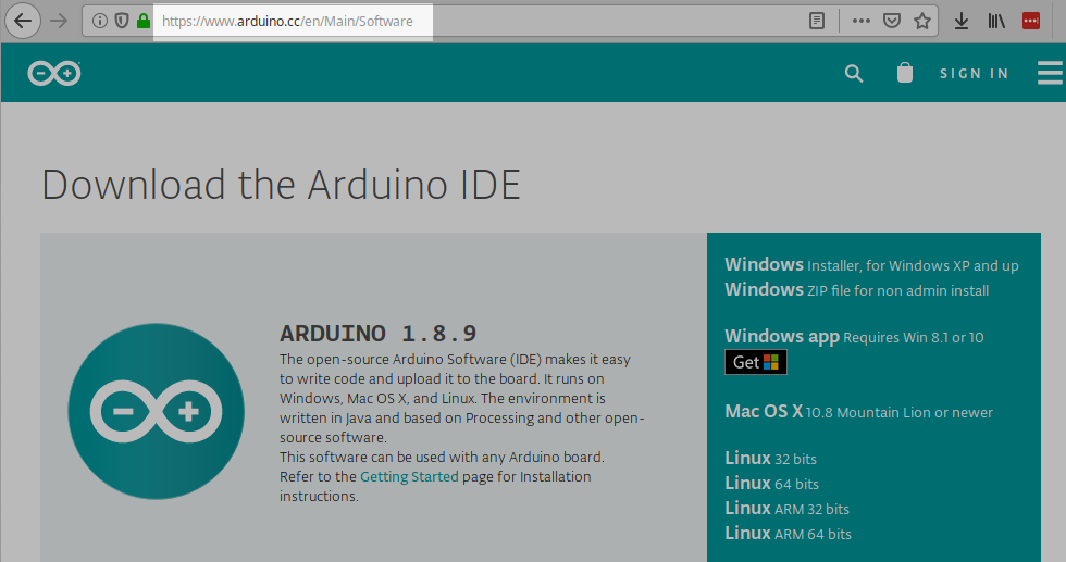 We suggest downloading the ZIP file. Expand it into your Desktop folder. Then go to
the Control Panel and use the Device Manager to update the driver.
We suggest downloading the ZIP file. Expand it into your Desktop folder. Then go to
the Control Panel and use the Device Manager to update the driver.
