
|
||
| Network Testing and Emulation Solutions |
|
|
||
| Network Testing and Emulation Solutions |
The LANforge-GUI is a graphical management interface to the LANforge system. The GUI connects to the LANforge manager process, which automatically discovers the LANforge Data Generators (also called 'Resources') on its management network. Because the connection to the server is a standard TCP/IP interface, the GUI can access the server remotely, even over a low bandwidth connection. The GUI has extensive 'tooltip' support, so if you are unsure of what a particular field or option box does, momentarily position the mouse cursor over the field of interest and view the brief description.
Clicking the HELP button will pop up a new window using your default browser displaying the section of the LANforge-GUI User Guide relating to the selected tab on the GUI display.
You can resize and re-arrange most tables in the GUI by dragging the columns around. You can use right-click options to select which table columns to display, save the current configuration, and return the table to the default values.
NOTE (Windows Vista users): Clicking HELP will direct your default browser to the Table of Contents of the LANforge-GUI User Guide and not to the specific section. From the Table of Contents, you can click on the section desired.
For a some ideas on how to test specific architectures and protocols, see
the cookbooks:
LANforge-GUI FIRE Cookbook and
LANforge-GUI ICE Cookbook.
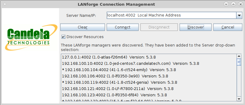
After installing the LANforge-GUI, you are ready to begin. First, start up the LANforge-GUI by double-clicking the anvil icon on the desktop. After clicking OK on the End User Licence Agreements, three windows should pop up, one of which is a login window that looks something like this:
NOTE (Windows Vista users): LANforge-GUI must be run as administrator from the desktop shortcut or Start menu.
Enter the name or IP address of the LANforge server that you wish to connect to. If you are running the GUI on the same machine as the LANforge server, then you can enter 'localhost' here. Note that the default server port is 4002, but this could be different depending on how the LANforge server was installed. You can also click the Discover button to have the GUI discover other LANforge systems on the local subnet. NOTE: The discovery process may be inhibited if the machine running the GUI has a firewall enabled.
Newly discovered systems are added to the drop-down menu and can then be selected. After entering the correct information or selecting the server from the drop-down menu, click the Connect button, and the GUI will attempt to connect to the server. If the server is re-started, or if the connection from the GUI to the server is lost for any other reason, the GUI will attempt to reconnect to the server every 5 seconds.
The last 20 servers that you logged into will be added to the drop-down menu for ease of use when re-connecting. If you ever want to re-initialize the list, remove the lfcnf.txt file that is in the LANforge-GUI installation directory and re-start the GUI. A new file will be created the next time you connect to the server.
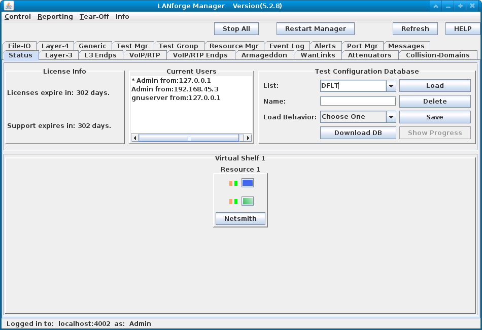
After you have connected to the server, the splash screen will disappear and the LANforge Manager window will appear with the Status tab displayed:
The Status Tab contains the following management panels:
The database files are stored in plain text, and are human readable. It is possible, though not necessarily advisable, for you to edit the databases by hand, or auto-generate them with a custom script.
To find the actual database files, look in the /home/lanforge/DB/ directory on the LANforge machine. The current configuration is saved to the 'DFLT' database every 30 seconds. A backup database will be also saved every 10 minutes with the name 'day_XXX' with XXX corresponding to the ordinal (Julian) date. To save the current database under specific name, enter it in the Name field and click the Save button.
Downloaded databases are saved below the LANforge GUI client current directory. On Linux, the path is /home/lanforge/saved_dbs, and Windows C:\Program Files\LANforge-GUI_5.2.8\saved_dbs.
Note on appending: it is possible to append databases that conflict. For example, two configurations could each have a cross-connect named "cx1." The last definition wins, and the results may look a little messy.
Each Resource has a certain number of 'ports' displayed which are color-coded according to their function:
The color of the two small squares to the left of each 'port' indicate the current Link Rate and Link Status for that port. Some drivers may not support port-speed reporting in a manner that LANforge can detect, but LANforge will continue to function normally other than reporting the wrong link speed. The leftmost square (Link Rate) will be:
The middle square (Link Status) will be:
The port layout is specified in a config file for each Resource and should have been configured correctly during installation. The tool-tip for each port indicates the interface identification, alias, and port status. Clicking on a port displays the Port Mgr tab with the specified port selected (highlighted) to provide detailed information.
LANforge includes the Netsmith graphical configurator for virtual routers, LANforge-FIRE, and LANforge-ICE testing scenarios. Please be aware that the Virtual Router functionality only works when the LANforge resource servers are running on Linux. The updated iputils program and the Candela kernel (or a kernel with the Candela patch applied) are also required. If you purchase a LANforge system (as opposed to software-only), this will all come pre-installed. If you are installing the software on your own system, please read the install guide(s) carefully.
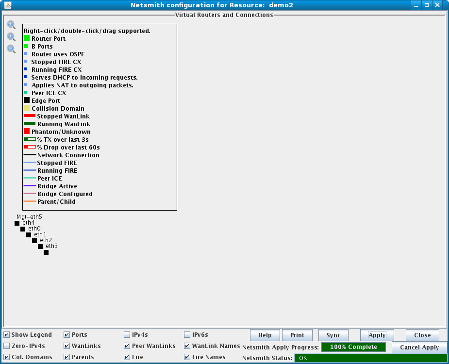
Open Netsmith by clicking the Netsmith button located below the resource of interest on the Status tab Virtual Shelf panel. When the Netsmith tool is first opened, it will auto-create as much as possible based on the current system configuration and resources. The positioning of the objects will most likely need to be changed. For most objects, just click-and-drag them to the new location using the mouse. Some objects, such as FIRE cross-connect (CX) representations are not independently draggable, but you can drag the port endpoints to reposition the FIRE CXs.
Click on the magnifying glass icons on the upper left of the Netsmith display to zoom-in, reset to default, and zoom-out, respectively.
Objects can be easily moved within the Netsmith display to suit your personal preference. Individual objects can be moved by left-clicking and draging to the new location. A selection box can also be created to move a group of objects by first left-clicking and draging to outline a box of the desired size. The selection box with its contents can then be dragged to a new location on the Netsmith display. The location of the selection box can be fine-tuned by using the left/right/up/down arrow keys while holding down the Ctrl key. Single objects can be moved in a similar manner by first selecting them with a single mouse click. Once the object is in the desired location, click the Apply button to save the changes.
In general, you can click-and-drag to move, double-click to modify, and right-click on objects to get a menu of available actions for each object or group of objects.
Here is an example of how to create a simple routed network emulation using
three physical ports and one virtual router. This will emulate a central
location with a 10Mbps network connection, and 2 remote sites with 1.54Mbps
T1 connections, all connected through a routed network.
For more examples,
please see the LANforge-GUI FIRE
Cookbook
and LANforge-GUI ICE Cookbook.
| Step | Screenshot |
|---|---|
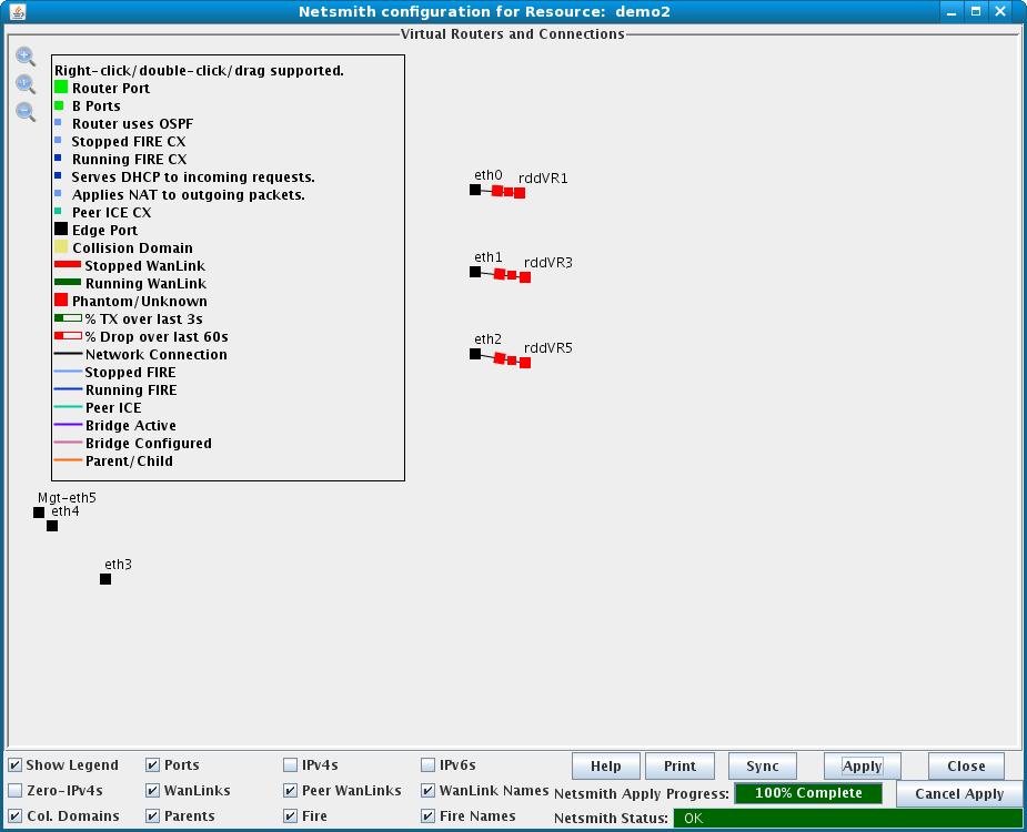
| 1. Open the Netsmith tool by clicking the Netsmith button located on the bottom panel of the Status tab display. |
|
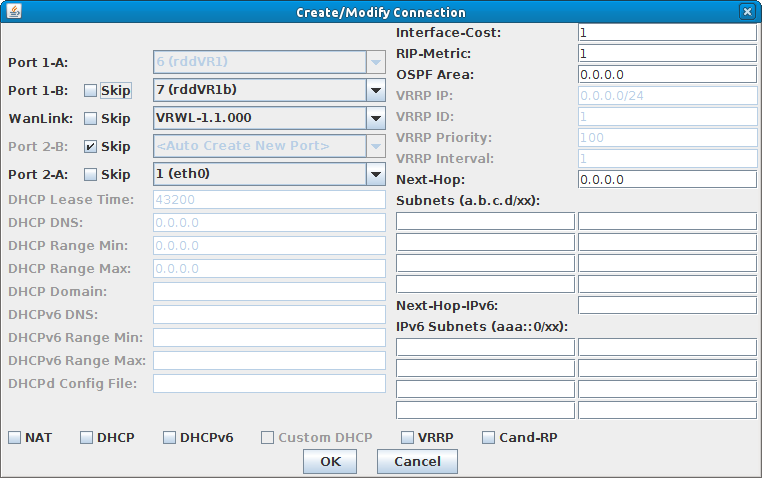
| 2. Three ethernet interfaces will be used in this example: eth0, eth1, and eth2. Ethernet interfaces can be clicked and dragged from their default location at the bottom-left corner of the display to the center for clarity. Clicking the Apply button at the bottom-right of the Netsmith window will save their locations on the display. Double-click eth0 to display the Create/Modify Connection window and modify its connection. |
|
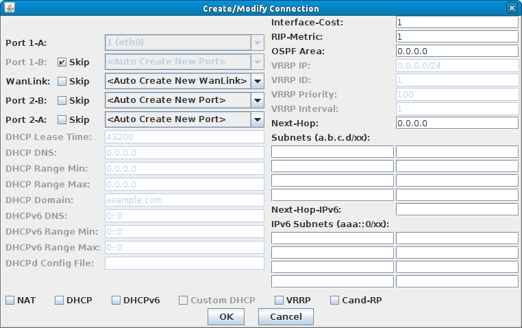
| 3. Deselect the 'Skip' checkbox to the right of 'WanLink:', 'Port 2-B:' and 'Port 2-A' to "un-skip" these connections in the Create/Modify Connection window. This will automatically create new entities as needed. Click OK to save the changes. |
|
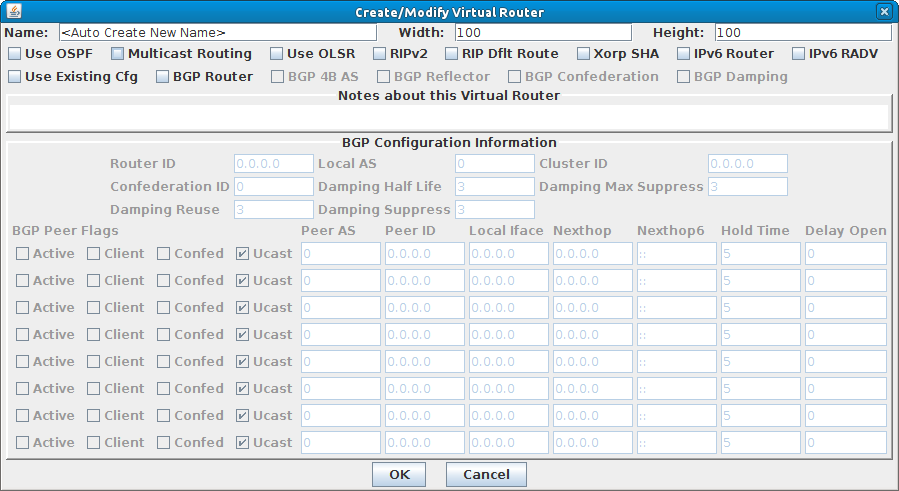
| 4. Double-click eth1 and eth2 and follow the same steps as above. When completed, right-click in a blank area within the window and select 'New Router.' This will display the Create/Modify Virtual Router window. |
|
| 5. A router name will be automatically assigned (e.g., R0) or a different name can be typed in the 'Name:' field if desired. Click OK when complete. |
|
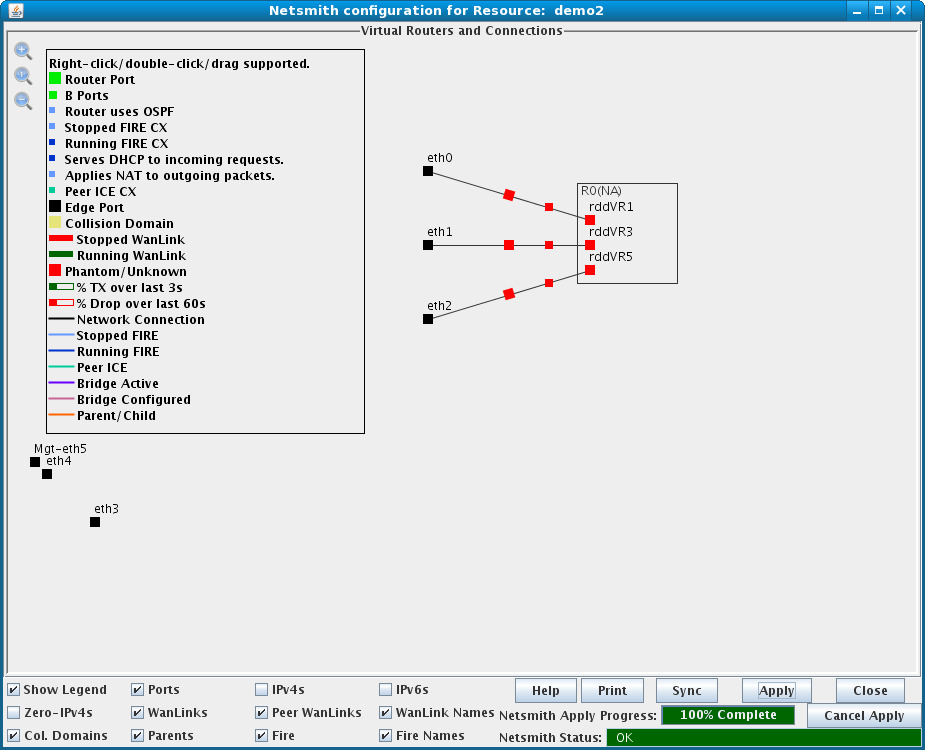
| 6. Drag the rddVRXX sides of the connections into the newly created virtual router. Click the Apply button to create the new ports and WanLinks. |
|
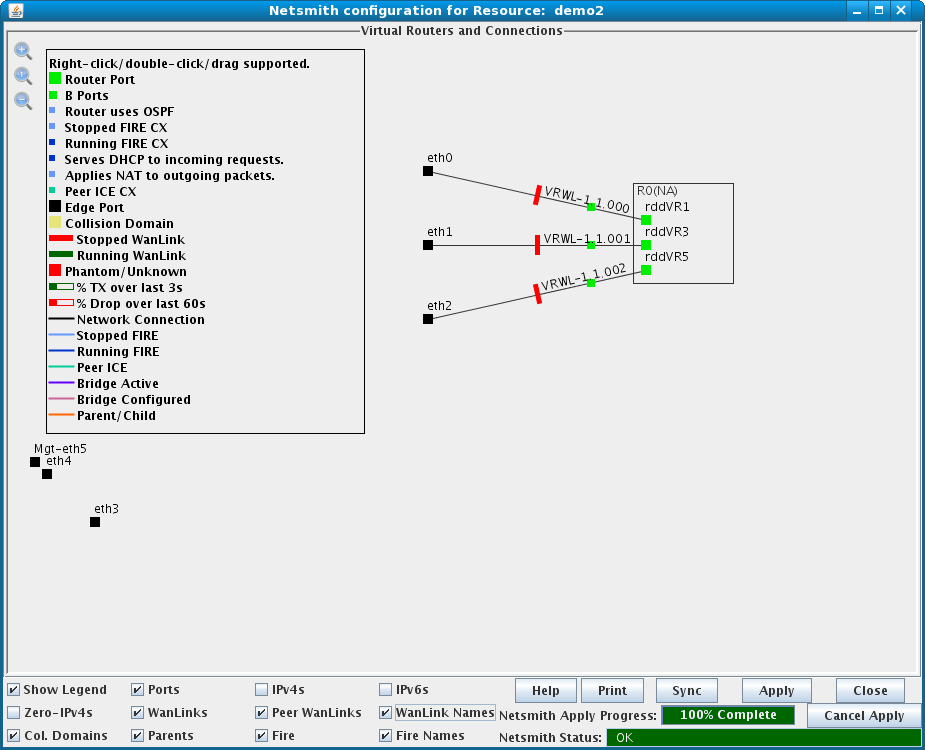
| 7. You should see the newly created objects go from red squares to green and black boxes. The WanLinks (red rectangles) will turn green when started. |
|
| 8. Right-click on each rddVRXX interface in the virtual router and select 'Modify Port' to add the appropriate IP Address, IP MASK, and Gateway IP. The default gateway for each port will be the IP address of the corresponding rddVRXX port in the virtual router. Selecting the 'IPv4s' or 'IPv6s' checkboxes on the bottom panel will display IPv4 or IPv6 addresses, respectively, on the Netsmith display. |
|
| 9. If this is to be part of a larger routed network, then you can double-click the port(s) in the virtual router and set the 'Next-Hop' and up to eight subnets that will be using this next hop. Please note that 0.0.0.0/0 is a valid subnet, and simply means 'ANY.' This is one way to set the default gateway for all unknown traffic. Click OK when done modifying the Virtual Router. |
|
| 10. When all of the ports in the Virtual Router have appropriate IPs, and the connection has the proper next-hops and subnets, click Apply to flush the changes to the LANforge server and create the proper routing tables. | |
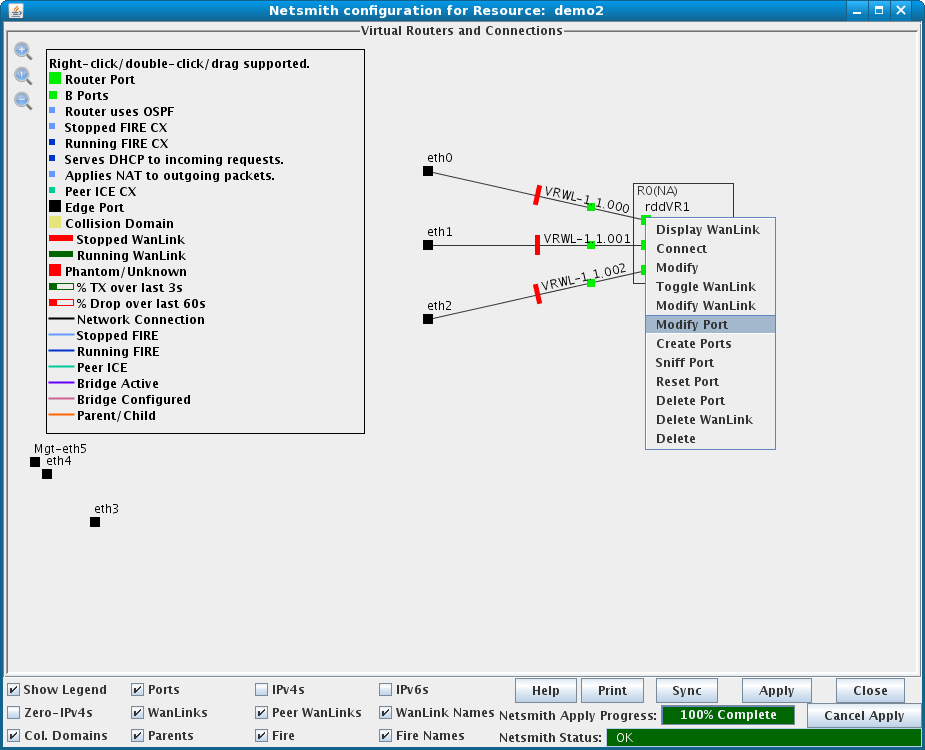
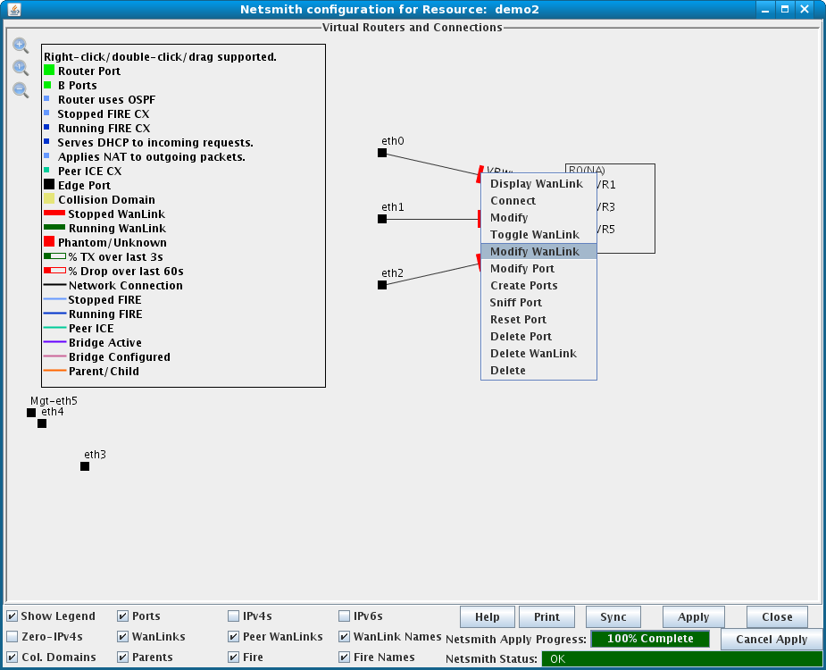
| 11. Modify the WanLinks by right-clicking the green (running) or red (stopped) rectangles and selecting 'Modify WanLink.' Set the transfer rate to 10Mbps on one, and 1.54Mbps on the other two. Set latency and other changes as required and click OK |
|
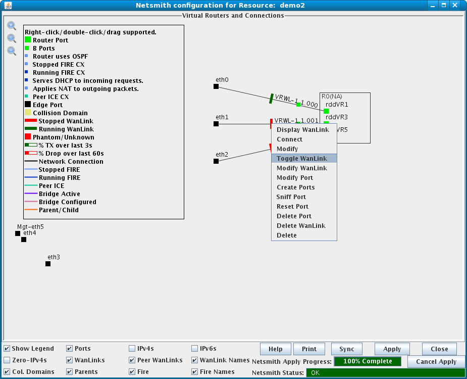
| 12. Start each WanLink by right-clicking its colored rectangle and selecting 'Toggle WanLink.' After completing changes in Netsmith, click the Apply button to flush the changes to the LANforge server. |
|
| 13. Connect your network equipment to ports eth0, eth1, and eth2. Your network equipment should now be able to ping through LANforge and you should see the latency that was configured in the WanLinks. |
To create a new Virtual Router, right-click in a blank area within the Netsmith window and select 'New Router.' This will bring up the Create/Modify Virtual Router window:
LANforge will generate a name automatically unless one is entered. The name, graphical size, notes field and other router configuration flags can all be modified when created or at a later time. The virtual router will use simple subnet routing rules unless otherwise directed. Xorp must be installed before using the following routing features: OSPF, Multicast, RIP, Xorp SHA, or BGP.
After creating a virtual router, existing interfaces can be dragged into it or new virtual devices can be created and associated to it. In order to be accessible to outside objects, however, the Virtual Router must either contain an interface (Port) that connects to the outside world or be connected to another Virtual Router that eventually connects to the outside world.
Netsmith Connections are used to connect routers to each other and to connect routers to the outside world. To create a new Netsmith Connection, right-click in a blank area within the Netsmith window and select 'New Connection.' This will bring up the Create/Modify Connection window:
You can choose up to 4 ports and one WanLink to be part of this connection. The number and combination of ports/WanLink selected changes the behavior significantly. In the example below, it is assumed that Port-1 will be the 'outside' port, but Router Connections do not have an inherent direction...it all depends on how you configure it.
Most objects have right-click menus associated with them to perform various actions. You cannot click on the connecting lines or the 'B' ports at this time.
The Netsmith window provides a real-time view of WanLinks and other LANforge entities. A movable legend is displayed in the upper-left portion of the Netsmith window. Edge ports appear as solid black squares and are accompanied by a red outline if the port has no link. Any objects drawn as a solid red square are not currently found in the LANforge system, even though the Netsmith has been configured such that they (should) exist. This can happen if interfaces or WanLinks were removed after Netsmith had discovered them, or if new WanLinks or connections have been created in Netsmith, but the changes have not been Applied yet. If these should really be deleted, just right-click and delete the offending objects and Apply the changes.
The checkboxes at the bottom of the Netsmith window can be used to display or hide various details to suit the user's preference. Selecting or deselecting these flags will not affect the actual configuration of LANforge in any way.
The LANforge security and administration framework has a concept of Clients (users), Test Managers, and Cross-Connects. A Test Manager is a grouping of one or more Clients and zero or more Cross-Connects. Any Client registered with a Test Manager can manage any of the Cross-Connects assigned to that Test Manager. As a special case, WanPaths can also be assigned to a Test Manager.
When you first log into the LANforge system through the GUI, you will be logged in as the user 'default'. The GUI will then try to log you in as user 'Admin'. If a password has been set for Admin and if the user 'default' does NOT have Administrator privileges, that login will fail and the login window will pop up to allow the user to change users and/or enter the correct password. If only a few different testers will be using LANforge at a given time, you may never need to create a new user. And if you are not concerned about who uses LANforge, there is no need to set an Admin password. It may be useful, however, to do so if you have a larger group of users or if communication between the users is not easy.
To log in as a particular user, select 'Client Admin or Login' from the Control pull-down menu. You will get a screen that looks like this:
Existing clients are displayed in the left panel. To view or modify client details, double-click the name in the left panel. Client details including name, Admin status, and some other flags are displayed on the right. Click Set to save any changes. To log in as a Client, double-click the client name in the Existing Clients list, enter a password if one is set, and click Login As. To create a new Client, enter a new name, set appropriate flags, enter a password if desired, and click Set. To delete an existing Client, double-click it, and click Delete.
Flags
Creating a Client for use by the CLI interface can be done through the GUI as well. Unless you are using some sort of scripting program to control the CLI, it is advised that you uncheck both Send Updates flags, or the CLI will be so noisy that you will not be able to see what you are doing!
By default, LANforge requires no password and the GUI will log in each Client as a super-user. To make LANforge more secure, deselect the Administrator flag from the default Client, then set a password for the Admin Client. You cannot set a password on the default Client, and a 'default_tm' Test Manager will always exist with the associated 'default' Client. To restrict the default Client's access, create a new Test Manager that does not include the default user, and add Cross-Connects to it.
Passwords may be reset by any Client selected as Administrator. Passwords are stored in a plain text file on the LANforge server at [LANforge-Home]/DB/passwd. If this file is deleted, all Clients will be able to log in without a password. This password protection will help keep Clients from accidentally interfering with configurations that they should not have access to, but should NOT be considered a serious means of securing the LANforge machine.
NOTE: LANforge is not designed as a highly secure application. You should ensure that the LANforge system cannot be accessed by un-authorized users on IP ports 4001 and 4002 through the use of firewalls or similar restrictions. Please contact LANforge support if you need more detailed information on securing LANforge.
A Connection Group is a collections of tests (Layer-3, WanLinks, VOIP, etc) that can be easily managed as a group. This includes starting, stopping and running scripts. Connections can belong to more than one Connection Group, but a Connection Group can only start if none of it's CXs are running in another Connection Group.
To create a new Connection Group, select the Connection Group tab and click Create. This will bring up the Create/Modify Connection Group window:
After creating the Connection Group, the Connection Group tab will display a summary of all existing Connection Groups and allow starting and stopping them. You can right-click for some additional options.
A Test Manager is a construct that represents a particular view into the LANforge system. In most cases, the default Test Manager can satisfy routine uses and the creation of addtional Test Managers is not required. Each Test Manager can have a selection of Cross-Connects and a list of Clients who are authorized to use the Test Manager. This allows one to set up multiple different tests on a LANforge system and quickly change the view to different test sets.
To create a new Test Manager, select the Test Mgr tab and click Create. This will bring up the Create/Modify Test Manager window:
After creating the Test Manager, the Test Mgr tab will display a summary of all existing Test Managers, including the one just created. To modify a Test Manager, select it and click the Modify button. This will bring up the Create/Modify Test Manager window described above.
Layer-3 Cross-Connects represent a stream of data flowing through the system under test. A Cross-Connect (CX) is composed of two Endpoints, each of which is associated with a particular Port (physical or virtual interface). The Layer-3 tab displays connections 0-200 by default. Connection numbering is 0-based where 0 represents the first connection name. To display all connections or a specified range of connections, select 'all' from the View field drop-down menu or enter range values ([min]-[max]) in the View field, then click the Go button to display the new range of connections.
When creating a Cross-Connect (CX), the details of each Endpoint including the Shelf, Resource, and Port that the Endpoint resides on need to be specifed. In this way, you determine which data-generating port (which is connected to some port on the system under test) the CX's traffic will flow over. In order to create a CX, click the Create button on the Layer-3 tab which will bring up the Create/Modify Cross Conect window:
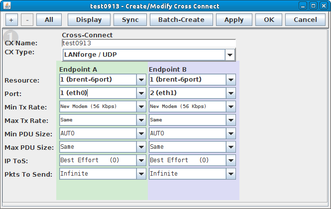
The modify screen displays the first configuration section which is sufficient for creating the CX. You may expose further details by pressing the "+" button in the upper right hand corner, or use the keystrokes control + and control -. There are five sections for this screen. Some fields are only valid for certain protocols and will remain greyed out unless that protocol is selected.
After the desired settings have been entered, click Apply or OK to create the Cross-Connect.
NOTE: A series of tests based off the current configuration can be created by clicking the Batch-Create button.
Sections of the Create/Modify Cross Connect window labeled Cross-Connect contain information relating to the entire CX, including the name, CX Type, Report Timer, and the Test Manager. There are Cross-Connect settings in sections 1, 2, and 3.
Custom Ethernet can be used to specify the exact pattern of bytes to transmit onto the Ethernet wire, including the Ethernet header. Additionally, the LANforge replay feature can replay Ethernet packets captured by LANforge-ICE, Wireshark or any other application that supports the 'pcap' packet capture format. When replay is selected, LANforge plays the packets exactly as they were captured, including the same Ethernet headers, transmission rates, etc. You may choose the Dest Mac option to re-write the destination MAC address for the packets being replayed. This may help make sure the network under test accepts the packets.
To replay a capture file, select the appropriate filename for each endpoint. For more information on generating the capture files, please see the Dump Packets notes in the LANforge-ICE section. LANforge can also replay standard pcap format packet dumps. It is possible to use the PcapPlusPlus utilities to split pcap streams. Here is an example of splitting a stream using bpf-filter syntax:
$ PcapSplitter -f lf-mcon.pcap -m bpf-filter -o . -p "src 1.1.1.3"
This will generate a file from the lf-mcon.pcap capture that has traffic eminating from endpoint with IP 1.1.1.3. Use both files when creating the Custom Ethernet connection. (Other pcap editing utilities also exist: editcap comes with WireShark, and tcpreplay-edit comes with tcpreplay).
This connection type also activates a GUI feature that allows you to build your own custom TCP/IP packets. Because LANforge has almost no control over what you send, it cannot detect received packets on the other end of the connection. You can use traffic sniffers or look at the port counters to get ideas of how many packets were actually received. See Configuring Payloads.
Custom Ethernet endpoints will receive, count, and throw away frames accepted by the port the endpoint runs on. This includes any packets sent by other LANforge connections. If the port is put into PROMISC mode, the port may even receive frames destined for other MAC addresses. So, received packets/bytes/bits-per-second stats for Custom Ethernet protocols should be used with care.
The left and right form columns of each info panel are used to define endpoints A and B. They are labeled TX Endpoint and RX Endpoint and are respectively colored green and purple. Endpoints are generally symmetric for UDP and Ethernet. For TCP/IP, the TX endpoint acts as a client, and the RX endpoint acts as a server (it waits for connections). Selecting different options may enable/disable certain fields.
For UDP and TCP protocols, the packets on the wire will never exceed the port's MTU + Ethernet-Header-Length (1514 on normal Ethenet ports). If the maximum is larger than the minimum, then each packet will be a random size between min and max.
NOTE: When using IPv4 or IPv6 multicast, LANforge may have trouble receiving PDUs that span multiple frames. So, a maximum payload size of 1472 is suggested. Please contact support if you want more details on this restriction.
NOTE: When running LANforge in Windows, QoS must first be setup by following the instructions in the Microsoft Knowledge Base article 248611: http://support.microsoft.com/default.aspx?scid=kb;EN-US;q248611
A series of tests can be created based on the CX Name and other current settings in the Create/Modify Cross-Connect window by using the Batch-Create function. For best results, create a valid connection for the first in the series to be batch-created, select the connection and click Modify. Clicking the Batch-Create button at the bottom of the window will pop up the Layer-3 Batch Creator:
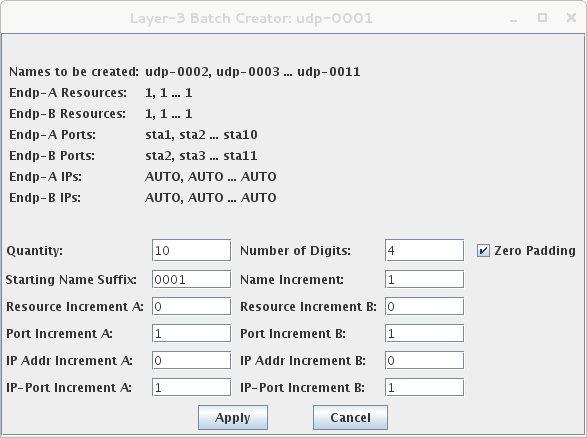
After the desired settings have been entered, click Apply or OK to create the series (batch) of Layer-3 Cross-Connects.
The Payload button allows for the configuration of custom payloads if a custom CX Type has been selected. A payload from a previous packet capture can be copied/pasted or one can be created by entering data into the various fields. For a Custom Ethernet Endpoint, clicking the Defaults button followed by Apply in each panel of the Configure Payload window will create a payload that looks something like this:
As you fill in the lower protocol layers (for instance, the Ethernet header), other protocol builders will be added to the GUI display as selected. For example, if you choose the IP protocol in the Ethernet header, the IP builder will appear. It will parse the top ascii-HEX window if possible and initialize its fields appropriately. From the IP protocol builder, you can choose TCP as the next layer, and the TCP builder will appear. Clicking the Apply button in each panel transfers the hex to the appropriate portion of the payload. The Apply All Protocols button at the bottom of the window can be used instead of the individual Apply buttons if desired. When finished, click Apply or OK to save the protocol to the selected endpoint.
LANforge supports several protocol builders. If a builder is not available for a protocol you wish to transmit, you can always paste a captured packet, or hand build one in HEX and transfer it to the text editor at the top of the Payload panel.
You can also initialize most protocols to defaults, and the resulting values will correspond to live packets gathered from our network. The ethernet protocol is slightly different, see the notes below. Make sure you initialize from the lower layers up to the higher layers.
Protocol builders for 802.1Q VLAN, ARP, IP-IP, IPX, LLC/SNAP, and MPLS labels have recently been added. Please let us know if there is a particular builder you would like to see implemented and more can be added in a future release.
Individual Cross-Connects can be selected for display from the Layer-3 tab. Select a Cross-Connect and click the Display button to bring up a summary window for that cross-connect.
The Cross Connect display is divided into three panels. The left and right panels describe information for endpoints A and B, respectively. The center panel describes the number of confirmed packets flowing and dropped from left-to-right and right-to-left, as indicated by the arrows.
The busy graphs on the right of each panel display the packet latency distributions for each endpoint. LANforge detects latency with a timestamp in each (non-custom) LANforge protocol packet. The precision is to 1 millisecond. If the two endpoints are using NTP protocol to keep themselves in sync, then they are usually within 0-3 milliseconds apart. Because of this, latencies may be negative at times. This just shows the difference in the clocks, and by looking at both sides of the connection, you can deduce the true round-trip latencies. For the best latency measurements, have both the sending and receiving port on the same machine. For even higher precision, consider an Armageddon endpoint, which has microsecond latency reporting.
LANforge only counts the latencies when it receives the packet. This is not exactly the time that the packet was received by the LANforge hardware because the packet must flow through the protocol stacks up to the LANforge server. This is the primary cause of the range of latencies you will see reported even on a simple and fast LAN. The average is usually very close though: It is a running average of the last 100 packets received.
Two latency graphs are displayed for each endpoint. The upper graph reflects latencies counted in the last 30 seconds, and the lower graph for the last 5 minutes. The upper right portion of each display widget lists the average latency (in milliseconds), width, and min/max latency within the respective time period. The color-coded numbers on the upper left of each widget are counters for each latency 'bucket' and are represented by the vertical bar graph below it.
The units for the size of the buckets are milliseconds, and are logarithmic (2^X) in scale. The exponential values (1, 2, 4, 8, etc.) will be multiplied by the bucket 'width' (currently always 1), and added to the minimum latency. For instance, if the minimum latencies for the top and bottom are 30 and 10 milliseconds, respectively, then the range of the first several buckets for each will be:
            31:
            32:
            34:
            38:
            46:
            ...
and
            11:
            12:
            14:
            18:
            26:
            ...
Assuming the minimum is 30, if the bucket "1" has 2000 beside it, then that means that 2000 packets have been received in the last time-period that had less than 31 milliseconds of latency. If the bucket "2" has 30 beside it, then that means 30 packets had latency between 31 and 32 milliseconds.
The minimum latency can change over time, which will cause the buckets to shift their values. Although this may be confusing at first, it allows LANforge to report high-precision data regardless of the latency of the system under test.
When viewing the Spreadsheet output, the lat_0, lat_1, etc columns show the number of packets received in the last 30 seconds that fall into the buckets.
As of release 5.1.2 and later, a Layer-3 Cross Connect can be scripted via the LANforge GUI so that the user can setup a single connection to run at different rates and payload sizes for various durations. Release 5.2.7 includes improvements that allows iterating through Attenuations too (provided the user has a LANforge Attenuator) and running scripts on Connection Groups.
The Add/Modify Script window is divided into two panels. The top panel identifies the endpoint and defines the script type and scripting options. The bottom panel describes the script configuration.
The 2544 script allows implementing part of the RFC 2544 script and is generally used to test throughput performance at various packet sizes, and tx rates. For WiFi testing, Attenuation steps may also be added. The user may specify constraints that mark each iteration as pass/fail based on how it performs against the constraints.
The Hunt script automatically finds the highest speed that meets the constraints specified by the user. It can iterate through various packet sizes.
The scripts create text output when they are running, and when finished, the GUI can create some 2D and 3D graphs for Hunt and 2544 scripts. The script results are plain text, so they can be saved for later viewing. As of LANforge 5.2.7, there is not a clean way to 'load' old results, but you can just delete any existing script results and paste in old ones from a text editor. Click the Graphical Display button on the Script Report window to see the graphs. The Grapical Display may be saved to an HTML report (after optional adjustment of the 2D and 3D graphs).
Example Hunt Script Graphical results:
Although the Layer-3 tab will be used to stop/start/modify your (non-IGMP) CXs, the fine details of each Cross-Connect are displayed on the L3 Endps tab. If you select a CX on the Layer-3 tab by single-clicking on its row, the Endpoints associated with that CX will be selected when switching to the L3 Endps tab. The L3 Endps tab displays Endpoints 0-400 by default. Endpoint numbering is 0-based where 0 represents the first Endpoint name. To display all Endpoints or a specified range of Endpoints, select 'all' from the View field drop-down menu or enter range values ([min]-[max]) in the View field, then click the Go button to display the new range of Endpoints.
Bulk changes to Endpoint values can be performed easily via the L3 Endps tab. For example, if you want several of your Endpoints running at 56000bps then you can select them, and use the 'MIN Tx Rate' combo-box to set the desired value. Additional bulk changes can be made to selected Endpoints by clicking the Batch Modify button. Selected values from the drop-down menus will be applied to all selected Endpoints. Endpoint values marked 'NA' will remain unchanged. For more specific modifications, select the Endpoint in question and click the Modify button. Endpoints can also be modified through their respective Cross-Connect on the Layer-3 tab.
If you wish to see graphs for the received packets for a particular Endpoint, you can select one or more Endpoints and click on the Display button. The display of a sample Endpoint is shown here:
LANforge supports the IGMP UDP Multicast protocol. Because there is a one-to-many relationship, these Endpoints are not handled by the standard cross-connect paradigm. Instead, you can create multiple Endpoints, specifying one generator and zero or more receivers for a particular IGMP address/port pair. To create an IGMP Endpoint, click the Create button on the L3 Endps tab. This will bring up the Create/Modify Endpoint window. To modify an existing IGMP Endpoint, select it and click the Modify button.
LANforge can create Voice over IP (VoIP) calls between LANforge interfaces. You may also setup third-party phones to call LANforge or be called by LANforge.
VoIP consists of several protocols. LANforge currently supports the SIP (Session Initiated Protocol) emssaging protocol. The voice payload is transmitted with the Real Time Protocol (RTP) which runs over UDP. The Real Time Control Protocol (RTCP) is used for latency and other accounting, and runs over UDP with the same priority as the RTP traffic. The VoIP/RTP tab displays connections 0-200 by default. Connection numbering is 0-based where 0 represents the first connection name. To display all connections or a specified range of connections, select 'all' from the View field drop-down menu or enter range values ([min]-[max]) in the View field, then click the Go button to display the new range of connections.
When creating a VoIP Cross-Connect (CX), you specify the details of each Endpoint, including the Shelf, Resource, and Port that the Endpoint resides on. In this way, you determine upon which data-generating port (which is connected to some port on the system under test) the call's traffic will flow. In order to create a CX, click the Create button on the VoIP/RTP tab. This will bring up the Create/Modify VoIP Cross Connect window:
After the desired settings have been entered, click Apply or OK to create the Cross-Connect.
NOTE: A series of tests based off the current configuration can be created by clicking the Batch-Create button.
The top panel of the Create/Modify Cross Connect window contains information relating to the entire CX, including the name, CX Type, report timer, and the assigned test manager. The CX name must be unique in the LANforge system.
Each Endpoint can be configured independently of the other. The default is to have the 'A' endpoint call the 'B' endpoint. The 'B' endpoint can be un-managed, which means LANforge assumes that it is a third-party endpoint, such as a Cisco or Grandstream SIP phone.
                     # muzak.ogg == input file, can be almost any type of sound file.
                     # -U      == ulaw encoding
                     # -c 1    == one channel
                     # -b      == 1-byte encoding (8-bit)
                     # -v 1.1  == increase volume by 1.1/1.0 percent, optional
                     # -r 8000 == 8000 samples per second.
                     # /tmp/muzak.wav  == output file, has to be a .wav extension.
                     # resample -q1    == makes it sound better, evidently, I can't tell.
A series of tests can be created based on the CX Name and other current settings in the Create/Modify Cross-Connect window by using the Batch-Create function. For best results, create a valid connection for the first in the series to be batch-created, select the connection and click Modify. Clicking the Batch-Create button at the bottom of the window will pop up the VoIP Batch Creator:
After the desired settings have been entered, click Apply or OK to create the series (batch) of VoIP Cross-Connects.
Individual VoIP cross-connects can be selected for display from the VoIP/RTP tab. Select a cross-connect and click the Display button to bring up a summary window for that cross-connect.
The VoIP Cross Connect display is divided into three panels. The left and right panels describe information for endpoints A and B, respectively. The center panel describes the number of confirmed packets flowing and dropped from left-to-right and right-to-left, as indicated by the arrows.
The busy graphs on the right of each panel display latency and jitter distributions for each endpoint over the last 30 seconds. LANforge detects latency with the RTCP protocol. Jitter is determined from the timestamp on the received RTP packets. Note that the jitter calculation is made before the packet is processed by the RTP Jitter buffer.
The upper graphs reflect RTCP latency, and the lower graphs reflect jitter derived from the RTP packets. The upper right portion of each display widget lists average values for latency and jitter, respectively. Min/max values are displayed below the average. The color-coded numbers on the upper left of each widget are counters for each latency and jitter 'bucket' and are represented by the vertical bar graph below it.
The units for the size of the buckets are milliseconds and are logarithmic (2^X) in scale. For instance, if the average latency is 101 milliseconds, then the buckets will be:
               102:
               103:
               105:
               109:
               117:
               ...
If the bucket "102" has 2000 beside it, then that means that 2000 packets have been received in the last time-period that have less than 102 milliseconds in latency. If the bucket "105" has 30 beside it, then that means 30 packets had latency between 103 and 105 milliseconds.
Although the VoIP/RTP tab will be used to stop/start/modify your VoIP/RTP Call CXs, the fine details of each Cross-Connect are displayed on the VoIP/RTP Endps tab. If you select a call on the VoIP/RTP tab by single-clicking on its row, the Endpoints associated with that CX will be selected when switching to the VoIP/RTP Endps tab. The VoIP/RTP Endps tab displays Endpoints 0-400 by default. Endpoint numbering is 0-based where 0 represents the first Endpoint name. To display all Endpoints or a specified range of Endpoints, select 'all' from the View field drop-down menu or enter range values ([min]-[max]) in the View field, then click the Go button to display the new range of Endpoints.
Bulk changes to VoIP Endpoints can be performed easily via the VoIP/RTP Endps tab by selecting one or more endpoints and clicking the Batch Modify button. Selected values from the drop-down menus will be applied to all selected endpoints. Endpoint values marked 'NA' will remain unchanged. Endpoints can also be modified through their respective Cross-Connect on the VoIP/RTP tab.
Armageddon Cross-Connects require special Linux kernel features. If you purchased your machine from Candela, then these features will already be included. Otherwise, you should make sure you have installed the kernel patches or a pre-compiled kernel from Candela.
The Armageddon traffic generator can generate UDP packets with various IP and UDP header fields. It also generates TCP packets, however this is NOT stateful TCP, so it acts a lot like UDP in that it will not back-off, and does not use any real TCP protocol features. More importantly, it can generate packets at line speed on 10/100/1000 Mbps and Multi-Gigabit Ethernet networks. Armageddon can also measure latency with 1 microsecond precision, and the sending and receiving ports can be on the same machine.
NOTE: If you are running Armageddon on a flat (non-routed) network, then LANforge can figure out all the defaults for you. However, if you are running in a routed network, you will need to manually enter the MAC address of your router in the Destination MAC field of the Armageddon section 2 configuration panel.
Bulk changes to Armageddon Endpoints can be performed easily by selecting one or more endpoints and clicking the Batch Modify button. Selected values from the drop-down menus will be applied to all selected endpoints. Endpoint values marked 'NA' will remain unchanged.
When creating an Armageddon CX, you specify the details of each Endpoint, including the Shelf, Resource, and Port that the Endpoint resides on. In this way, you determine which data-generating port (which is connected to some port on the system under test) the CX's traffic will flow over. In order to create an Armageddon CX, click the Create button on the Armageddon tab. This will bring up the Create/Modify Armageddon Endpoint window:
Sections of the Create/Modify Armageddon Endpoint window labeled Cross-Connect contain information relating to the entire CX, including the name, CX Type, Report Timer, Test Manager, Quiesce, and Relative-Timestamps. There are Cross-Connect settings in sections 1 and 2. The name must be unique in the LANforge system.
The left and right form columns of each info panel are used to define endpoints A and B. They are labeled TX Endpoint and RX Endpoint and are respectively colored green and purple. Selecting different options may enable/disable certain fields.
WanLinks support the LANforge WAN/Network emulation feature set called LANforge-ICE. In the default WanLink configuration, two interfaces act like a transparent layer-2 ethernet bridge. The WAN emulation is applied as traffic flows through this bridge. Each WanLink is composed of two WanLink Endpoints that represent one of the sides of the WAN/Network emulation. WanLinks can apply various characteristics to traffic flowing through them including maximum-bandwidth, latency, jitter, jitter-frequency, dropped-packets, duplicated-packets, reordered-packets, bit & byte errors, and more!
A WanLink emulates a bridged Ethernet network with characteristics determined by the user. Packets are received in one Ethernet (or virtual) interface and are transmitted out the other interface. This means that when you add the LANforge machine to an existing network configuration, no routing changes are needed. When designing your network, you can think of a pair of WanLink ports as an ethernet switch or even just a pass-through cable! WanLinks can bridge 802.1Q VLAN, Ethernet and Redirect interfaces.
LANforge-ICE supports multiple virtual routers per system when LANforge is running on Linux. On Windows, only bridge-mode is supported. Use the Netsmith tool described earlier in this guide to configure LANforge-ICE in the routed mode.
LANforge-ICE works best using a minimum of three ethernet ports: two for each WanLink and the third to access the LANforge machine remotely for management purposes. To ensure that there is no interaction with the LANforge machine's protocol stacks, the IP address for each WanLink port is automatically removed.
It is possible to run WanLinks on a machine with only two ports, but you will not have the option to manage LANforge remotely unless you cleverly configure some virtual interfaces. In this scenario, your machine will need to be configured for a loopback device to manage LANforge. See the LANforge Server Installation Documentation for how to configure a loopback device on your machine. NOTE: There are work-arounds for even this restriction if you use a more complex Netsmith setup with bridge devices. Contact support if you have such a need.
Bulk changes to WanLink Endpoints can be performed easily by selecting one or more endpoints and clicking the Batch Modify button. Selected values from the drop-down menus will be applied to all selected endpoints. Endpoint values marked 'NA' will remain unchanged.
When creating a WanLink, the details of each WanLink Endpoint must be specified, including the Port where the WanLink Endpoint resides. This determines which port the WanLink will use for receiving traffic. The peer endpoint's interface will be used for transmitting packets. In order to create a WanLink, click the Create button on the WanLinks tab. WanLinks can be attached to Ethernet, Redirect, and 802.1Q VLAN interfaces. WanLinks should NOT be directly attached to MAC-VLAN, 802.11a/b/g, or PPP interfaces at this time.
The WanLink Create/Modify screen expands from configuration section 1 to
section 5. Use the + button to expose new configuration
sections. You may also use keystrokes
The top section of info sections 1, 2, and 4 of the Create/Modify WanLink window contains information relating to the entire WanLink, including the name, resource, report timer, test manager, and presets.
For example, on our E3 v3 processor system, this configuration can run full 10Gbps line speed:
WanLink (on eth4, eth5) using CPU id 3
            eth4 using CPU-mask 0x1
            eth5 using CPU-mask 0x2
To set the Ethernet port's CPU-mask, you also have to manually disable the IRQ balance daemon as root user:
systemctl stop irqbalanceIf you wish to use general-purpose features later, it is usually best to re-enable irqbalance.
The settings for each WanLink Entry Point apply to packets entering the Port associated with that endpoint.
Most equipment that you will find in any network will contain a certain amount of buffers to smooth bursty traffic so that packets are not needlessly dropped. The backlog buffer is your way of configuring this value. The units are in multiples of 1024 bytes (1KB). The size of the buffer depends on many things, and should generally be larger for higher-speed simulations. Due to the bursty nature of Ethernet (and ethernet drivers in common systems), we suggest these buffer sizes when trying to simulate a relatively well structured WAN:
| WanLink Speed | Backlog Buffer Size |
|---|---|
| 56Kbps - 256Kbps | 2-8 |
| 257Kbps - 1.54Mbps | 8-32 |
| 1.5Mbps - 45Mbps | 32-256 |
| 45Mbps - 155Mbps | 256-1024 |
| 155Mbps - 1Gbps | 1024-8192 |
| 1Gbps - 10Gbps | 8192-65536 |
Selecting AUTO will set the backlog such that it can hold at least 10 ms of data at the configured speed. It will hold more than 10ms of packets at slower speeds in order to accomodate small bursts of packets. For instance, if the rate is 10Mbps, AUTO mode will cause the backlog to be set to 62KB. The actual backlog size is shown in the WanLink Endpoints table.
The Min and Max Offset fields determine the location of the corruption. If Min is less than Max, the corruption will be at a random byte between Min and Max.
If the Chain-to-Next checkbox is selected, any time this corruption is applied, the next corruption will be applied as well. This can allow you to reliably generate multiple corruptions in a single packet.
If the Checksum checkbox is selected, LANforge will attempt to recalculate the IPv4, UDP, and TCP checksum for the packet after applying the corruption. This will allow the errored packet to be accepted by the stacks on the receiving machine as if the data were actually valid. This feature will only work if the UDP or TCP payload does not span more than one physical ethernet frame. The ethernet checksum (FCS) is not controlled by LANforge at this time, and will always be recalculated by the network adapter on transmit.
WanPaths represent a virtual WAN between a source and destination IP or MAC Address range. This allows you to set up one WanLink that simulates a physical pipe, and multiple WanPaths that simulate connections between different machines or sets of machines on your network. You can have up to 128 WanPaths on each WanLink endpoint.
The configuration of a WanPath is similar to that of a WanLink, except that the WanPath belongs to a specific WanLink, and you must specify the IP Address ranges (or other match criteria) that are to match this WanLink.
Please note that when you add a WanPath to an endpoint, the patterns match with regard to packets entering the interface that the endpoint uses. If you want to match on a source IP of 192.1.1.2 and the endpoint is configured on eth0, then put that machine on the network connected to eth0.
After creating a WanLink, you may display it to watch the flow across your emulated WAN in detail. To display one or more WanLinks, select the row(s) and click the Display button.
Individual WanPaths can also be displayed by selecting one or more WanPaths and clicking the Display Selected Paths button at the bottom of the window.
As of release 5.1.2 and later, a WanLink can be scripted via the LANforge GUI so that the user can setup a single WanLink to run with different rates, latencies, jitter and drops for various durations.
The Add/Modify Script window is divided into two panels. The top panel identifies the endpoint and defines the script type and scripting options. The bottom panel describes the script configuration.
A full sample report from the WanLink script showing results for each iteration and a summary of
transmit and
receive packet statistics plus link utilization can be found at:
examples/wanlink-scripted/Scripted-WanLink-Text-Report.txt
LANforge 5.2.7 introduces support for the LANforge Attenuator system. The attuator is used for testing WiFi systems by decreasing (attenuating) the RF signal as it flows through the attenuator. This allows one to emulate having an AP and WiFi station very far apart while sitting comfortably in the lab. To use the attenuator, plug the attenuator's USB cable into your LANforge machine and then click 'Refresh' on the Attenuators tab in the LANforge GUI. The attenuator information should appear in the Attenuators tab a few seconds later.
To configure an Attenuator, select the Attenuators tab and click Modify. This will bring up the Modify Attenuator window:
Collision Domains complement the LANforge WAN/Network emulation feature set (LANforge-ICE) by allowing the user to associate multiple WanLinks in a group with an aggregate rate limitation. This feature is useful for emulating wireless networks where several links may allow high speeds individually, but the associated Access Point allows a fixed total throughput. For example, you could configure ten 36Mbps speed WanLinks, each with their own impairment profile, into a Collision Domain that is rate limited to 54Mbps. This would limit the group of WanLinks to no more than 36Mbps individually and 54Mbps combined, emulating the effect of having a WiFi collision domain on the network under test.
After creating a set of WanLinks, go to the Collision-Domains tab and select Create. The WanLinks that you created will be displayed in the right-hand (Free WanLinks) column. Move the WanLinks to be associated with the Collision Domain to the left-hand (Associated WanLinks) column by selecting them and clicking the <<–– Add CX button. After the desired settings have been entered, click Apply or OK to create the Collision Domain.
NOTE: Adding Virtual Routers to a Collision Domain is not supported at this time.
The top panel of the Create/Modify Collision Domain window contains information relating to the Collision Domain, including the name and report timer. You can also select the Shelf and Resource that the Collision Domain will reside on. For LANforge-ICE systems with only one machine, you do not need to change these values from their default of one (1).
To view the Collision Domain while it is running, go to the Collision-Domains tab.
You can also use Netsmith to view the graphical representation of your Collision Domain.
File Endpoints are used to generate file system traffic. If you happen to configure LANforge to have file systems mounted over NFS, iSCSI, CIFS, or SMB (SAMBA), then the file system tests will indirectly produce network traffic as well. A file endpoint is synonymous with a file cross-connect, because LANforge only controls or manages a single side. The other side may be either the local file system or a remote NFS server: It makes no difference to the LANforge software suite's configuration. LANforge on Linux supports virtualization of NFS and CIFS clients, allowing one system to emulate several thousand clients. This can be useful for testing file-servers and WAN acceleration technologies.
Bulk changes to File Endpoints can be performed easily by selecting one or more endpoints and clicking the Batch Modify button. Selected values from the drop-down menus will be applied to all selected endpoints. Endpoint values marked 'NA' will remain unchanged.
When creating a File Endpoint, you get to specify attributes such as file size, how many files, read vs. write, chunk-size to read/write and some options relating to synchnonizing (flushing) the files to disk. A File Endpoint is a complete test by itself (you do not directly create File Cross-Connects as you do with some other endpoint types). In order to create a File Endpoint, click the Create button on the File-IO tab. This will bring up the Create/Modify File Endpoint window:
After the desired settings have been entered, click Apply or OK to create the Endpoint.
NOTE: A series of tests based off the current configuration can be created by clicking the Batch-Create button.
On kernels older than 3.7, the option is 'directio' instead of 'cache=none', for
example:
username=lanforge,password=lanforge,directio
A series of tests can be created based on the Name and other current settings in the Create/Modify File Endpoint window by using the Batch-Create function. For best results, create a valid endpoint for the first in the series to be batch-created, select the endpoint and click Modify. Clicking the Batch-Create button at the bottom of the window will pop up the File-IO Batch Creator:
After the desired settings have been entered, click Apply or OK to create the series (batch) of File Endpoints.
You can now create endpoints with these protocols: HTTP, HTTPS, FTP, FTPS, TFTP, SCP and SFTP. These are stateful protocols that will communicate properly with third-party servers. FTP, FTPS, TFTP, SCP and SFTP can upload and download, and the other protocols are only for downloading. The Layer 4-7 tab is used to manage Layer 4-7 endpoints.
To Create a new Layer 4-7 endpoint, click on the Create button. This will bring up the Create/Modify L4 Endpoint window. To modify a layer 4-7 endpoint, select the endpoint(s) and click the Modify button. You will see a window that looks like this:
After the desired settings have been entered, click Apply or OK to create the Endpoint. NOTE: A series of tests based off the current configuration can be created by clicking the Batch-Create button.
If you would like to have LANforge act as an FTP server, modify a port and under Services enable FTP. If you are on release 5.2.7 or lower, please see the /home/lanforge/local/sbin/ct-vsftpd-notes.txt file on the LANforge machine for directions on setting that up properly.
If you wish to use anonymous FTP upload, make sure the URL points to a directory within
/var/ftp, for example, ftp://10.0.0.2/testdir/upload-file.txt . The directory should be
owned by the ftp user (see below commands to create a directory and change ownership).
Create directory: mkdir /var/ftp/testdir
Change directory owner: chown ftp:ftp /var/ftp/testdir
Note: If you are using a LANforge release prior to 5.3.5 you will need to enable
anonymous uploading by adding the below two lines to the
/home/lanforge/vr_conf/vsftpd_PORT.conf file after the line
userlist_enable=YES.
After the change, reset the port that has FTP enabled:
anon_upload_enable=YES
anon_other_write_enable=YES
Some URLs include:
                            log Starting telnet session
                            dl telnet://192.168.100.6 /tmp/fs2-telnet.txt
                            expect login: user
                            expect Password: password
                            expect ]$ ls
                            expect ]$ exit
                            done
                            log Done with telnet session.
Another option is to have a list of URLs in a file on the LANforge data generator machine. In that case, you specify that filename (relative to /home/lanforge) and the Layer 4-7 Endpoint will process every URL in that file, over and over again. A file might look like:
                      # Format is:
                      # [ul | dl] 'URL' 'filename'

                      # Get default web page from lf1
                      dl http://172.1.1.103/index.html /tmp/172.1.1.103_index.html

                      # Get default web page from lf4
                      dl http://172.1.1.103/index.html /tmp/172.1.1.103_index.html

                      # Get a file via FTP
                      dl ftp://172.1.1.103/pub/gnuserver /tmp/172.1.1.103_gnuserver

                      # Put a file via FTP
                      ul ftp://172.1.1.103/pub/upload/gnuserver.upload /tmp/172.1.1.103_gnuserver

                      # Log a message to LANforge logs
                      log This is the message that will show up in the logs.

                      # Sleep for one second (1000 ms)
                      sleep 1000

                      # expect [input] [output]  Only works with Telnet currently.
                      expect login:  user

                      # Done with telnet connection.
                      done

                      # Call a system command (Used to generate a new email text in this case)
                      # The environment variable LFL4_SYSCNT will be set to the number of times
                      # the system call as been executed while processing this script.
                      system 'update_email_txt.pl > /tmp/smtp_script_mail.txt'

                      # Set some values in the Layer 4-7 Endpoint
                      set smtp_from support@candelatech.com
                      set rctp_to <customer1@foo.com><customer2@foo.com>
A series of tests can be created based on the Name and other current settings in the Create/Modify L4Endpoint window by using the Batch-Create function. For best results, create a valid endpoint for the first in the series to be batch-created, select the endpoint and click Modify. Clicking the Batch-Create button at the bottom of the window will pop up the Layer 4-7 Batch Creator:
After the desired settings have been entered, click Apply or OK to create the series (batch) of Layer 4-7 Endpoints.
Individual Layer 4-7 connections can be selected for display from the Layer 4-7 tab. Select a connection and click the Display button to bring up a summary window for that connection.
The graphs on the right side of the Layer 4-7 Endpoint display window show the latency distributions for various measured parameters in milliseconds. The top left graph shows the latency distribution of the time it took to receive the first byte of data from the server. The top right graph displays the distribution of the time it took to complete the URL request from beginning to end. And the bottom left graph indicates the latency distribution for DNS lookups.
LANforge only counts the latencies when it receives the packet. This is not exactly the time that the packet was received by the LANforge hardware because the packet must flow through the protocol stacks up to the LANforge server. This is the primary cause of the range of latencies you will see reported even on a simple and fast LAN. The average is usually very close though: It is a running average of the last 100 URLs received.
The upper right portion of each display widget lists the average latency (in milliseconds), width, and min/max latency within the respective time period. The color-coded numbers on the upper left of each widget are counters for each latency 'bucket' and are represented by the vertical bar graph below it.
The units for the size of the buckets are milliseconds, and are logarithmic (2^X) in scale. The exponential values (1, 2, 4, 8, etc.) will be multiplied by the bucket 'width' (currently always 1), and added to the minimum latency. For instance, if the minimum latency is 30 milliseconds, then the range of the first several buckets for each will be:
         31:
         32:
         34:
         38:
         46:
         ...
Assuming the minimum is 30, if the bucket "1" has 2000 beside it, then that means that 2000 URLs have been received in the last time-period that had less than 31 milliseconds latency. If the bucket "2" has 30 beside it, then that means 30 packets had latency between 31 and 32 milliseconds.
The minimum latency can change over time, which will cause the buckets to shift their values. Although this may be confusing at first, it allows LANforge to report high-precision data regardless of the latency of the system under test.
When viewing the Spreadsheet output, the lat_0, lat_1, etc columns show the number of packets received in the last time period that fall into the buckets.
LANforge has the ability to control command line tools and collect their results. For example, the 'ping -I eth4 172.1.1.2 -s 1024' command will ping to host 172.1.1.2, using the local interface eth4. The command must not redirect standard-out, or LANforge may not be able to properly stop the test. It is up to the user to specify the correct command line, but Candela Technologies will be happy to offer suggestions and help with any tools you would like to use in this manner.
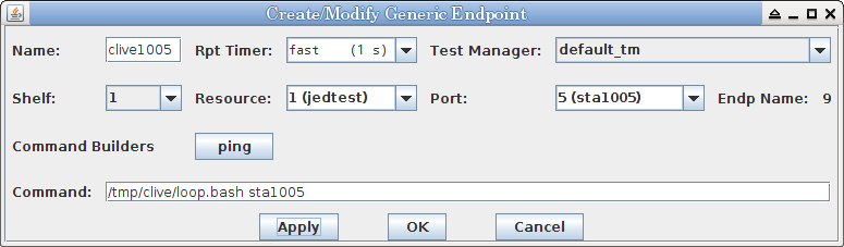
To Create a new Generic endpoint, click on the Create button on the Generic tab. To modify, select the Endpoint(s) and click the Modify button. You will see a window that looks like this:
Subject: Test Email./smtp-client.pl --enable-auth --verbose \
This is a test email.
This example is known to work with Fedora releases 19-21 that use the 0.4.x versions of clive. Newer releases of Fedora use the 0.9.x version of clive which does not appear to work well with the quvi package.
To effectively download YouTube videos, you need to install the clive program (as found in Fedora 17 or later, the version using the quvi utility).
sudo yum install clive # Fedora 17 sudo apt-get install clive # Ubuntu 12.04
There are scripting files to accompilish this in /home/lanforge/generic:
Start by creating 10 wifi station endpoints, sta1001 — sta1010 and getting them to associate with their wifi access point. Next, setup a directory for a series of clive configs. You will then create a clive config file for each port. (Example now uses /var/tmp because /tmp is often memory-backed and a large test could make your system start swapping.)
$ mkdir /var/tmp/clive
$ ln -s /var/tmp/clive /tmp
$ ln -s /home/lanforge/generics/clive_loop.bash /tmp/clive/loop.bash
$ ln -s /home/lanforge/generics/clive_battery.txt /tmp/clive
$ cd /home/lanforge/generics; ./create_n_clives.bash sta 1001 1010 10.99.99.2
Following this, test one of your clive config files on the command line:
$ export LD_LIBRARY_PATH=/home/lanforge/local/lib
$ CLIVE_CONFIG=/tmp/clive/clive_sta1001.config /usr/bin/clive -O /tmp/clive/video.out 'http://www.youtube.com/watch?v=Bqu1Vq1r4Gs'
$ ls -lh /tmp/clive/video.out   # check the file size
$ file /tmp/clive/video.out     # check that it is not a html file
If you do not get a video downloaded, please try these steps:
--get-with "nice -n 19 /home/lanforge/local/bin/curl -qv -m 30
 --max-redirs 1
 --connect-timeout 10
 -sLki -4 -c '/tmp/clive/curl-eth1.cookie'
 -b '/tmp/clive/curl-sta1000.cookie'
 --interface 'sta1000'
 --localaddr '192.168.100.28' --dns-servers '8.8.8.8'
 --dns-interface 'sta1000'
 --dns-ipv4-addr '192.168.100.28'
 -C - -o %f %u --user-agent 'Mozilla/5.0' "
Proceed to run the test command (beginning with CLIVE_CONFIG= ...)
$ dig -t 192.168.100.28 @8.8.8.8 www.youtube.com
$ host www.youtube.com
www.youtube.com is an alias for youtube-ui.l.google.com.
youtube-ui.l.google.com has address 172.217.11.174
youtube-ui.l.google.com has IPv6 address 2607:f8b0:4007:80d::200e

$ ping -I 192.168.100.28 172.217.11.174
For each station, you will enter the shortened version of the command that calls the loop:
Name: clive1001 Port: (sta1001) Command: /tmp/clive/loop.bash sta1001
Continuing, you can then create your 10 generic endpoints using the endpoint config.
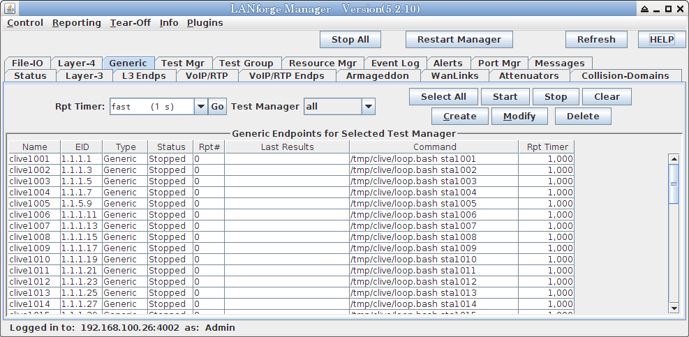
When you are confident that your clive endpoints are downloading, in the Generic tab you can highlight all endpoints and click Start to start all scripts downloading.
The LANforge system uses the term 'Resource' to apply to a data-processing machine. The Resource Mgr tab displays information on all Resources discovered by the LANforge server and provides the ability to perform system functions on selected machines (one or more). Clicking the Netsmith button will open a Netsmith display window for the selected Resource(s). Clicking the Restart LANforge button will restart the LANforge server on the selected Resource(s). Clicking the Reboot Machines button will reboot the operating system on selected Resource(s). Clicking the Shutdown Machines button will shutdown the operating system on the selected Resource(s).
If a resource indicates 'Phantom', then the LANforge server is not running on it, or the LANforge manager is unable to communicate with it for some reason. You will not be able to manage a Resource in this state. If the Resource is not Phantom, then you can also reboot the Resource OS, or shutdown the OS for good (i.e., until a power-cycle of the individual Resource.)
If you have LANforge systems in a geographically disperse deployment, you may wish to connect them to a GPS device to automatically obtain their location. LANforge supports this feature, and all you need to do is configure the right serial port settings using the lfconfig tool. You may also manually enter the coordinates using the CLI.
The Serial Spans tab is used to manage T1 and E1 spans and channel groups. T3 and other higher speed interfaces may be supported in the future. Currently, Digium T1 cards and Sangoma T1 and E1 cards are supported.
LANforge cannot currently detect the T1/E1 spans automatically, so you must add them through the GUI if your system is not pre-configured. Click the Create button in the Serial Spans (T1) panel of the Serial Spans tab. This will bring up the Create/Modify Serial Span window:
After creating a Serial Span, you can now configure one or more channel groups on the span. Digium T1 cards support up to 24 channel groups per span, but the Sangoma cards we have tested only support 1 channel group at this time. Click the Create button on the Channel Groups panel of the Serial Spans tab. This will bring up the Create/Modify Channel Group window:
The PPP connections will run over one or more T1 channel groups, and PPPoE interfaces can be created over regular ethernet (assuming you have a PPPoE server available). If you choose more than one channel group, then the multi-link PPP protocol will be used.
The basic building block of the ppp daemon is the pppd server. If you only use Sangoma T1 hardware or PPPoE, the default pppd on modern distributions will work. LANforge creates a start script in the pppScripts directory. When the PPP link is started, LANforge will fork and exec this script.
To create a PPP connection, click Create from the PPP-Links tab. This will bring up the Create/Modify PPP-Link window:
The Event Log tab is used to record interesting events. The user may also create custom events. This may help users correlate test results with certain events, such as link up/down, starting and stopping of tests, etc. Suggestions are welcome for more events of interest.
The text message in the events can be modified by the user. Double-click the event, or use the right-click popup-menu to bring up the Create/Modify widget.
They can also be logged to a file and the default priorities can be overridden. Each event type can also be filtered out if the user is not interested in it. To modify these settings, click the Configure Events button, and modify the values in the resulting window:
The Alerts tab is used to display current alerts in the system. This includes interfaces that are not connected and similar problems. As of release 5.2.4, only a few Alerts are supported, but more will be added in future releases. Suggestions are welcome.
The Port Mgr tab represents the individual Ethernet Ports and other virtual interfaces on the LANforge Data Generators (Resources). It has a large number of counters whose values are acquired from the kernel drivers. Each port can be configured with an IP address (and must be configured if you are running anything other than raw Ethernet protocols or LANforge-ICE) and a default gateway. The Default Gateway will be used when the system-under-test acts as a router. LANforge is designed to make each port look as if it's a separate computer, so you are able to specify a different default gateway on each port, or the same one if you desire. You are not restricted to the use of Port IP addresses, except that you must not have duplicate IP addresses on the same Resource, and of course they must make sense in whatever testing network you have configured. TCP/IP networking can be complex, so if you have questions not addressed here, email support@candelatech.com and they will explain how LANforge can address your specific needs.
LANforge can also give you easy access to some ethernet driver configuration options, including various link speeds and auto-negotiation settings. This, of course, will only work if you have the cards and ethernet drivers which support these features.
The buttons on the top panel of the Port Mgr tab are used to view and manage individual ports.
As of LANforge version 5.3.2, the Batch Modify Ports screen expands from one to five panels:
| Basic port settings | |
| Basic WiFi settings | |
| Advanced WiFi station options | |
| Advanced WiFi AP options | |
| Additional WiFi settings |
When you modify fields in the batch modify screen, they are highlighted so that you can quickly survey your changes before you apply them.
To modify a port configuration, select the port and click the Modify button. This will bring up the Configure Settings window for the selected port. The available options depend on the type of interface being configured:
WiFi Radio (Wiphy) Interfaces, Firmware
The upper panel displays Port Status Information as currently reported by the
drivers. Port status will be updated automatically, but can also be updated
by clicking the Refresh button on the LANforge Manager window.
NOTE: With
Bypass hardware installed, the 'Current:' line will include one of the following
states: BYPASS-ENABLED, BYPASS-ENABLED BYPASS-SLAVE, BYPASS-DISABLED, or BYPASS-DISABLED
BYPASS-SLAVE.
The lower panel displays Port Configurables.
NOTE: The 'Set Bypass' checkbox, which allows for
setting the Watchdog timer and other Bypass functions, will only be enabled if hardware
support for the bypass feature set is detected.
The 'Enable' section of checkboxes on the left enables/disables configurable fields. Some options can cause port resets and other fairly intrusive behavior, so many options are disabled by default. LANforge can usually detect when no actual changes have been made, so do not worry too much about selecting more 'Enables' than required.
By default, LANforge will attempt to run the HTTP server on the standard port 80. This will conflict with the Apache web server running by default on the LANforge machine. To work around this, either:
To edit nginx, see comments at top of the auto-generated config file, and remove the first line if needed. Then, change the 'listen' line so that it looks something like this:
listen 4.3.1.2:8080 bind_dev=eth1;Restart nginx by these actions:
You may want to copy a large file into the /usr/local/lanforge/nginx/html/ directory so that you have something to download:
sudo ln -s /usr/share/dict/linux.words /usr/local/lanforge/nginx/html/
To create a WiFi Bridge, set exactly one non-STA interface to a wifi bridge ID and set at least one STA interface to that same bridge ID.
The algorithm will look at packets arriving on the non-STA interface and attempt to match the source MAC to the MAC of an STA. If it finds the STA, the packet will be bridged onto that STA and transmitted out the wireless interface. Packets arriving on the STA interfaces will be bridged onto the non-STA interface. If the destination MAC is broadcast, it will be re-written to be the MAC of the STA.
The MAC of the STA must therefor exactly match the MAC of the external device being bridged. To bridge more than one external device, additional WiFi station interfaces should be created, using the MACs of the external devices.
Interfaces in a WiFi bridge should not have any IP addresses configured, and should not be running any other LANforge traffic such as WanLinks, Armageddon, Layer-3, etc.
The buttons located at the bottom of the window provide functionality in addition to the standard Apply, OK, and Cancel.
LANforge supports virtual WiFi stations (Virtual STA) interfaces when LANforge is used with supported WiFi NICs. Currently, only certain Atheros 802.11a/b/g and 802.11a/b/g/n NICs are supported.
NOTE: Testing shows that at least some WiFi NICs will lock up if B and not A is selected, so if using a subset of channels, use A or A+B instead of B or B+C. Contact support if you have any questions on this.
                    ctrl_interface=/var/run/wpa_supplicant
                    fast_reauth=1

                    network=(
                        ssid="foo"
                        key_mgmt=WPA-EAP
                        eap=PEAP
                        identity="user"
                        password="user-password"
                        phase1="auth=MSCHAPV2"
                        priority=10
                    )
HS20 and EAP-AKA:
On 5.2.11, the '3GPP Cell Net' field was mislabeled '802.11u ANQP'.
Its tooltip is correct, however. The AP's MCC and MNC must match the
EAP Identity for the stations in order for the ANQP query to match
the AP. The MCC and MNC is the first part of the EAP Identity.
HS20 Realm and Domain should also be configured on the station.
Certain hardware supports port pairs physically looped together in a 'master-slave' configuration to be set in Bypass Mode, creating a single logical wire. With bypass hardware installed, the state of each module will be listed on the 'Current:' line of the Port Status Information pane for that port:
This status will be set on the 'master' port of a Bypass Pair when the 'Bypass' checkbox is
selected. This port and its 'slave' peer are in bypass mode.
NOTE: When a Bypass Pair
is in Bypass-Enabled state, only the master port LED on the NIC will indicate link status
and LANforge will not show link status on the Status tab. When a port pair is in bypass mode,
it acts as a single physical cable.
This status will be set on the 'slave' port of a Bypass Pair when the Master port is in the bypass mode.
This status will be set on the 'master' port of a Bypass Pair when the 'Bypass' checkbox is not selected. This port and its 'slave' peer are in normal mode.
This status will be set on the 'slave' port of a Bypass Pair when the Master port is in the normal mode.
Bypass hardware can be configured via the Port Mgr tab or manually enabled via a running
WanLink connecting the peer ports. Modifying a selected port via the Port Mgr tab and
selecting the 'Set Bypass' checkbox enables the Bypass configuration functions on the right side
of the pane. The port pair can then be configured to operate in bypass mode immediately, on power-up or
power-down/loss of power. A Bypass Disconnect mode can also be selected.
NOTE: Although a running WanLink can be configured to override this behavior, affected ports will
revert to their default Bypass settings in the Port Mgr tab when the WanLink is no longer running.
The hardware can be set for WanLinks to 'fail open,' for example.
Several buttons at the bottom of the window allow saving configuration changes and other features.
LANforge has the ability to create and delete virtual interfaces on the fly. Six types of virtual interfaces are currently supported. You must have a (virtual) port-license for each VLAN that you create: Please contact sales@candelatech.com if you need more licenses. LANforge has no hard upper limit on the number of interfaces that can be created. Candela has tested up to 2000 MAC-VLANs on a high-end machine, with each virtual interface running Layer 4-7 HTTP requests. Support for these virtual interfaces requires the LANforge resource to be running on Linux, with the Candela kernel and updated iputils package. See the Installation Guides for more details if you are installing LANforge on your own machines.
MAC-VLAN virtual interfaces create the illusion of multiple real interfaces on a single interface. From the outside world, it appears as if the physical LANforge interface is an ethernet switch with multiple machines connected to it. In other words, the MAC-VLANs are completely transparent to the other machines on the network. MAC-VLAN interfaces can be created on physical ethernet interfaces, redirect, and 802.1Q VLAN interfaces.
LANforge also supports creation and deletion of 802.1Q VLANs. Unlike MAC-VLANs, 802.1Q VLANs speak a slightly different protocol on the ethernet network. This means that the systems that the LANforge machine is talking to must also be configured for 802.1Q VLANs. 802.1Q VLAN interfaces can only be created on physical ethernet and redirect interfaces.
Redirect-devices are a pair of virtual interfaces that are logically connected with a loopback cable on the far side. Redirect-devices are not directly associated with any physical interface. If rdd0 and rdd1 are a pair, then when you transmit a packet on rdd1, the packet will be automatically received on rdd0. This feature is used for configuring LANforge-ICE in router mode, and can also be used for demonstration purposes where physical interfaces are in short supply.
Bridge devices are Linux network devices that allow one to aggregate other network interfaces into a single broadcast domain. After creating a bridge device, it can be modified to include the network devices that are to be associated with the bridge. Logically, bridges are very similar to an ethernet switch. Bridge-devices can be configured for Spanning Tree Protocol to better emulate and interact with real world networks.
WiFi Virtual Station (Virtual STA) interfaces create
the illusion of multiple distinct WiFi stations (think: laptops with WiFi NICs)
using a single physical WiFi radio. To the Access Point(s) (APs)
it appears as if each Virtual STA is an individual station. Each Virtual STA has its own
MAC, IP address and routing table. All LANforge-FIRE related traffic
generation features work with Virtual STAs. Virtual STAs may only be created
on Radio (Wiphy) Devices.
NOTE: The only supported Radio hardware is certain Atheros/Qualcom
chipset NICs using special drivers provided by pre-built Candela kernels
and appliances.
WiFi VAP interfaces may only be created on Radio (Wiphy) Devices.
NOTE: Some Radio devices may have improper (or overly conservative)
regulatory domain settings. LANforge supports overriding the regulatory domain,
but if done improperly, this can put the system out of regulatory (FCC, in the USA)
compliance. Please contact support if you want information on how to change the
regulatory domain.
WiFi Monitor interfaces may only be created on Radio (Wiphy) Devices.
Monitor interfaces are primarily used for sniffing WiFi traffic. Only one
monitor interface should be created per radio. Just creating a WiFi Monitor
interface can decrease performance on the system, especially when using lots
of other virtual WiFi interfaces. Performance will go back to normal when the
monitor interface is deleted.
To create one or more virtual interface, select a port on the Port Mgr tab and click the Create button. This will bring up the Create VLANs window with the selected port as the parent device:
Select a VLAN type at the top of the window. When creating a MAC-VLAN, you must specify a MAC Address to uniquely identify this VLAN. When creating 802.1Q VLANs you must specify the VLAN-ID. For redirect-devices, just specify the two redirect names. We suggest rdd0, rdd1, etc, but you can also name them as regular ethernet devices if you wish (eth2, eth3, etc).
Multiple VLAN interfaces can be created at once by entering a Quantity greater than 1. Enter the beginning IP and/or MAC address and the create function will automatically increment the MAC and/or IP addresses. Selecting the DHCP-IPv4 checkbox will set all interfaces as DHCP-IPv4 clients to receive their IP address via DHCP. The remainder of the interface attributes can be modified following creation via the Modify button on the Ports tab. Newly created VLAN interfaces will be visible on the Netsmith display after clicking the Sync button.
Select the Use WPA checkbox to enable WPA and related wpa_supplicant authentication methods.
To delete a virtual interface, select it on the Port Mgr tab and click the Delete button.
If you have Wireshark installed and configured correctly on your LANforge machines, and if your machine upon which you are running the GUI supports the X-windows protocol, you may sniff a particular port. To sniff a port, select it and click the Sniff Packets button. You may have to change the DISPLAY option box under the Sniff Packets button if you have a non-standard setup. For example, if your LF GUI is running on one PC and your LF Server is on another, you would type in the IP address of the LF GUI machine with :0.0 at the end so that the LF Server would be allowed to display the Wireshark program on the LF GUI PC. For Windows PCs running the LF GUI, the cygwin program must be installed per the GUI installation instructions. When Wireshark pops up, you can start sniffing packets by clicking on the 'Capture' menu item.
LANforge currently supports two different RF Noise Generator platforms. The CT711 is based on an a/b/g/n USB NIC with customized firmware. The noise it generates is modulated (CCK, OFDM, HT). Because the signal is modulated, and it does not have better than about 20us precision, it is not good for RADAR emulation, but it can be used as a constant noise source for testing CCA. The CT711 is configured in the Port-Mgr tab, in the wiphyX radio configuration screen.
The CT712 RF Generator from Candela Technologies is a software-defined radio and can be used for RADAR emulation. It supports 1us precision pulse configuration. It generates non-modulated noise, so it can be used for that part of CCA testing as well. The CT712 is configured in the RF-Generator tab of the LANforge GUI. For some more details on RADAR, please see this page on DFS and RADAR patterns.
The FCC and ETSI buttons configure the pulse width, interval, count and other fields with values that match the respective buttons. For RADAR types that have a range of values, each time you click the button a new set of random values in the correct range will be configured in the config files. Click Apply to make them take effect.
See tooltips on the buttons with '*' after their label for notes on limitations for emulating certain RADAR types.
Pulse Width This specifies the duration (in micro-seconds) for the transmitter to be enabled. The user may type in a specific value, and the LANforge-GUI has pre-set values in pull-down menus for common FCC and ETSI radar patterns.
A pulse width of 0 means constant transmit. This is useful for CCA testing, especially when used with a programmable attenuator and RF analyzer.
The Messages tab is used to convey miscellaneous information from the LANforge server to the user. It can also be used to input CLI commands to the LANforge server. You can see an example of its output here:
The Save and Clear Text buttons only affect the LANforge Manager machine performing the actions and do not affect other machines which may be logged in to the LANforge server. Clicking the Save button will pop up a Save window so the contents of the text panel can be saved to the Manager machine. Clicking the Clear Text button will clear the message contents and replace them with a Day/Date/Time log entry.
With the release of 5.1.5, most tables in the LANforge-GUI now support automatic calculations of their numeric columns and user-selected rows. Select the rows you are interested in and use the right-click->Calculations menu item to bring up the calculations window.
The top section has three rows: Sum, Mean (Average), and Median. The Mean is the sum of all selected rows divided by the number of rows. The Median is the value in the middle of a sorted list of the column data.
The bottom section lists the deviations from the average for each selected row and the standard deviation for the entire column of data.
The deviation table rows may be sorted by clicking on a column header, and the data can be refreshed for the previously selected rows by clicking Refresh. It will not be automatically updated after the initial creation.
The four pull-down menus located at the upper left of the LANforge Manager window provide additional features and configuration options.
The main graph has two independent axes, with Axis B controls on the left and Axis A on the right. By default, data-sets other than Latencies are assigned to Axis A and Latencies are assigned to Axis B. The user can drag data sets from one axis to another by dragging the label at the bottom of the graph to the desired side.
A small button above each of the Axis labels selects that axis for actions that can work on either axis (mouse controlled zooming and clicking).
The vertical drag bars scroll the data associated with that axis up or down. If the mouse is released within the outer 10% of the drag bar, it is automatically re-centered to allow more adjustment.
To add data-sets, click on the Add/Remove button for Endpoints, Ports, or Connection Groups. After selecting the appropriate entities, use the Select Data button to choose your data-type options. You may also select the Global Stats checkbox to graph global data.
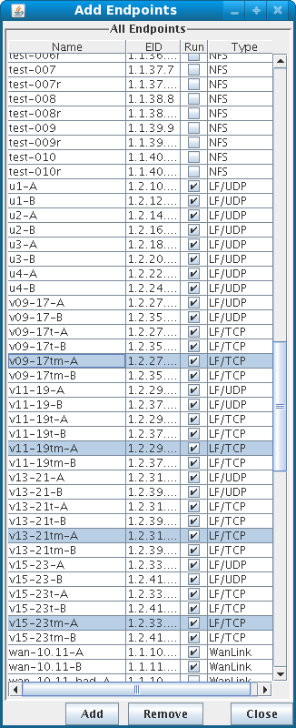 |
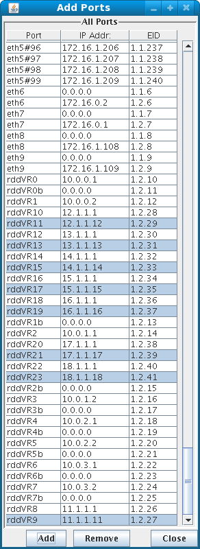 |
dynamic_reports
The Global Stats checkbox includes a running total of all running cross-connects. Assume two Layer-3 connections C1 and C2, where C1-A and C1-B are both transmitting at 10Mbits, and C2-A is transmitting at 10Mbps but C2-B is not transmitting. The Global Tx-Bps value for this scenario would be 30Mbps. Activity through the management port, or any port object is not collected in the Global Stats feature. This means that services outside of LANforge that are running on LANforge managed ports (like apache, nginx, or bind) that are transmitting will only be captured in individual port objects. To demonstrate, you can watch activity of two ports transmitting a ping command, and see that the Global Stats-RxBps value does not change.
Below is a list of values that the Global Stats feature can display. These values are selected from the Select Values feature next to it.
| LANFORGE_UDP | LANFORGE_UDP6 | CUSTOM_UDP | LANFORGE_MC_UDP | LANFORGE_MC_UDP6 | CUSTOM_MC_UDP | ARM_UDP | LANFORGE_TCP | LANFORGE_TCP6 | CUSTOM_TCP | L4_GENERIC | VOIP |
|---|
| Suffix | Description | |||||||||||
|---|---|---|---|---|---|---|---|---|---|---|---|---|
| TxPps | tx packets per second | |||||||||||
| x x x x x x x x x x x x | ||||||||||||
| RxPps | rx packets per second | |||||||||||
| x x x x x x x x x x x x | ||||||||||||
| TxBps | tx bits per second | |||||||||||
| x x x x x x x x x x x x | ||||||||||||
| RxBps | rx bits per second | |||||||||||
| x x x x x x x x x x x x | ||||||||||||
| TcpCx/s | TCP connections per second | |||||||||||
| - - - - - - - X - X - - | ||||||||||||
| Tcp6Cx/s | TCPv6 Connections per second | |||||||||||
| - - - - - - - - X X - - | ||||||||||||
| TcpCxActive | Tcp Active Connections | |||||||||||
| - - - - - - - X - X - - | ||||||||||||
| Tcp6CxActive | TCPv6 Active Connections | |||||||||||
| - - - - - - - - X X - - | ||||||||||||
| UdpTxBps | UDP tx bits per second | |||||||||||
| X X X X X X X - - - - X | ||||||||||||
| UdpRxBps | UDP rx bits per second | |||||||||||
| X X X X X X X - - - - X | ||||||||||||
| UdpTxPps | UDP tx packets per second | |||||||||||
| X X X X X X X - - - - X | ||||||||||||
| UdpRxPps | UDP rx packets per second | |||||||||||
| X X X X X X X - - - - X | ||||||||||||
| TcpTxBps | TCP tx bits per second | |||||||||||
| - - - - - - - X - X - - | ||||||||||||
| TcpRxBps | TCP rx bits per second | |||||||||||
| - - - - - - - X - X - - | ||||||||||||
| L4-URL/s | Layer 4-7 URLs requested a second | |||||||||||
| - - - - - - - - - - X - | ||||||||||||
| L4-TxBps | Layer 4-7 tx bits per second | |||||||||||
| - - - - - - - - - - X - | ||||||||||||
| L4-RxBps | Layer 4-7 rx bits per second | |||||||||||
| - - - - - - - - - - X - | ||||||||||||
| L4-Errors/s | Layer 4-7 errors per second | |||||||||||
| - - - - - - - - - - X - | ||||||||||||
| VoipActive | VOIP active sessions | |||||||||||
| - - - - - - - - - - - X | ||||||||||||
The Save and Stop buttons control the saving of reporting data. Clicking the Save button begins saving reporting data to .CSV files in the selected directory. Reporting data will continue to accumulate until the Stop button is clicked. Every Collect and Ignore cycle creates a new set of CSV files in addition to any existing CSV files.
Graphical HTML reports of selected Endpoints
can be created by clicking the Generate Report→Generate Report button any time.
NOTE: Manager Server and GUI Reporting are supported if using the LANforge LiveCD but all files must be saved to external storage media.
Generating Reports: Click the Generate Report→Generate Report button to pop up the Report Generator window which enables you to create a customized graphical HTML report. First, choose the directory where the .csv report data was saved. This should be the same location as in the previous step. Next, choose a main directory where the GUI will save the HTML reports. This directory will be the top-level directory under which all Report Name directories will be stored. Alternatively, the individual .csv files can be viewed directly by navigating to the Report Data Directory mentioned above and opening the files with a spreadsheet application.
After choosing your HTML report options select the Endpoints, Interfaces, and Resources that
should be included in the HTML report. When you have the data files you want selected, click
the Generate Report button.
The Report Generation Progress pop-up will present the entire status of report generation for each Endpoint, Interface, or Resource selected. The duration of report generation will depend on the size and number of .csv data files selected. At the conclusion of the report generation, the progress pop-up will confirm the name and directory of the completed HTML report. Your web browser will then be launched automatically to the index of the newly generated HTML report.
Up to this point, each tab has been shown as it appears among the collection of other tabs embedded in the main window. Selecting a tab from the 'Tear-Off' pulldown menu will display the selected tab in a new window. This will allow you to monitor several tabs at once! Click the 'Close Window' [X] button in the upper right corner of the window to return the tab to the main window. Below is an example of the Layer-3 tab tear-off:
The Info Menu provides information about Candela Technologies, Inc., as well as other useful information.
With the release of LANforge version 5.2.9, the LANforge GUI now supports plugin scripts written in the Groovy scripting language. This allows users to utilize the full power of the LANforge GUI to automate tasks, and generate customized reports.
Some scripts are included to provide useful features and to act as starting points for users who wish to write their own scripts. To view the current plugins, use the Plugins drop-down menu in the main LANforge GUI window. Some of the plugins are also right-click options on related tables in the LANforge-GUI.
Built-in scripts are automatically loaded (from the lflclient.jar) when the GUI starts (though later scripts could unload and/or replace them if desired). Next, all files in the user_groovy directory are loaded. If a user wishes to customize an existing script, they should copy it from example_scripts to the user_groovy directory and make changes. The modified script will first unload the default script before loading itself, it can also just load itself with a different name.
If using more than one station per radio/NIC (wiphy), then the stations can only roam to other APs on the same channel. If you want to roam across different channels, then delete all stations except for the wlanX and use those for the mobility test. To use this plugin, select the stations you wish to migrate on the Port-Mgr tab, right-click and choose WiFi Mobility.
For a detailed document on how to configure this, see: WiFi 802.11r Roaming HOWTO.
Select the stations that will be monitored. This does not restrict your script, but in general, you should select all stations that you are roaming in the script.
The Script Generator will take a list of BSSIDs placed in the text field on the right and generate a script for you to use in the Roaming Script tab. A warning message will be given at the bottom if an error is encountered. Use the below fields to customize how your script will generate.
The text field on the right holds the script. This is a set of text commands that will scan, sleep, and roam the stations. The text field on the left has some instructions on the syntax. In particular, you should scan on the target AP's channel 1-2 seconds before attempting a roam. Otherwise, the station may do an automatic scan which will significantly increase the amount of time it takes to complete the roam attempt.
Make sure that any station you wish to roam uses 'DEFAULT' for it's AP field in the Port-Modify screen. Otherwise, it will not be able to roam to an AP other than what it has configured.
Once everything is configured, click Start to begin the mobility test.
Interpreting results
A good AP setup should roam within 50ms when using 802.11r.
To use it, first create and configure Virtual Station interfaces so that they can connect to the AP(s). For upload or download testing, you must also have at least one non-station interface (typically a wired Ethernet interface) to act as the upstream side of the network. For station-to-station testing, just select an even number of stations and a connection will be made between each pair. Select the interfaces you wish to use on the Port-Mgr tab of the LANforge-GUI and choose launch the WiFi Capacity Test through the Right-Click menu or the Plugins pulldown menu. The script configuration screen should then pop up:
The configurable options are:
Click Start to start running the capacity test. As the script runs, a window of graphs and text is populated. The text may be edited by hand before saving (for instance, to add notes for this particular test). Graphs may be resized or otherwise adjusted. When satisfied with the layout, click Save File to generate an HTML report with the text and graph images.
The configurable options are:
This takes a collection of Layer-3 connections and slows them down until the maximum round-trip time is no more than 1 second over the average, and the total requested rate is less than 120% of the actual receive rate. This plugin is useful for throttling down WiFi connections that otherwise might run unfairly due to a few stations hogging all of the bandwidth.
For UDP connections, this may be the only way to see fairness on the network, but for TCP connections, any device-under-test with proper feature set and configuration could also enforce fairness without needing this plugin.
The configurable options are:
Here is a sample report generated by the Enforce Fairness plugin.
The configurable options are:
The configurable options are:
The configurable options are:
If you need transfer or remove these report profiles, they are in the LANforgeGUI directory, under the folders trb_entities and trb_profiles.
Open a terminal, and use these commands:
cd /home/lanforge/LANforgeGUI_5.3.1
mkdir user_groovy
cd user_groovy
wget http://guest:guest@www.candelatech.com/private/downloads/r5.3.1/port_reset.groovy
Follow these steps:
%USERPROFILE%\Local Settings\Application Data\LANforge-GUI_5.3.2Example:
C:\Documents and Settings\jreynolds\Local Settings\Application Data\LANforge-GUI_5.3.2On Windows 7 and newer, the LANforge installs in
%LOCALAPPDATA%\LANforge-GUI_5.3.2Example:
C:\Users\jreynolds\AppData\Local\LANforge-GUI_5.3.2
If you have having trouble with the LANforge GUI, here are a few techniques you can try to get information about your problem:
It is possible to install a copy of LANforge that lacks a Java runtime. Make sure you have Java installed. You can test this from the command line by running:
C:\> java -version
It is possible that you have downloaded a version of the LANforge GUI that has been compiled for another processor architecture. If you are running a 32-bit operating system, a 64-bit LANforge GUI will not run. If you use the command-line to start the GUI, it will tell you that the application will not run on your system:
C:\Users\bob> cd AppData\Local\LANforgeGUI-5.3.5
C:\Users\bob\AppData\Local\LANforgeGUI-5.3.5> .\lfclient.bat

Java: cannot execute lfclient.jar
Somemtimes the LANforge GUI becomes unresponsive. There are a number of possible causes for this, including:
The JRE running the LANforge GUI is configured to not use all the RAM on your LANforge by default. This is to allow other processes (the server processes and your desktop) to avoid experiencing memory pressure. This can leave RAM for reports.
On Linux since 5.3.9: Please use htop on your system before using the GUI -> Control -> JVM+Memory settings window.
On a Candela Technologies LANforge system, your GUI is located in /home/lanforge/LANforgeGUI-5.3.8 and the startup script
can be used like:
cd /home/lanforge/LANforgeGUI-5.3.9
./lfclient.bash
On Windows since 5.3.9: the memory settings file is at %LOCALAPPDATA%\lanforge\settings.bat (E.G. C:\Users\bob\AppData\local\lanforge\settings.bat). You can safely remove this file. Please use Task Manager to display how much free ram your desktop has when not running the LANforge GUI. If there are problems running the GUI on Windows, you can attempt to use %LOCALAPPDATA%\LANforgeGUI\lfclient2.bat to start with basic JRE 8 settings. E.G.:
On Windows LANforge 5.3.8 and earlier: You can edit the C:\Users\bob\AppData\Local\LANforgeGUI-5.3.8\lfclient.bat file. and change the -Xmx switch to give the application more memory. If you are using a 32-bit version of Windows or a 32-bit version of Java on a 64-bit version of Windows, you will be unable to allocate more than 3GiB of memory. Please consider using a 64-bit version of Windows and the 64-bit version of the LANforge GUI.
If you do have a GUI lockup, we want to know. Please run the LANforge GUI using the command line (as referenced above: AppData\Local\LANforgeGUI-a.b.c\lfclient.bat).
When the GUI locks up again, press the Thread Dump key combination: Ctrl+Break. This will not display a new window, but it will print a stack trace in the command window. Please email that output to us at support@candelatech.com and it will help us diagnose the problem.
If you are on the desktop of a Candela Technologies LANforge system, you can trigger a stack trace using the Ctrl+\ key combination. You can also use the commands kill -3 `pgrep java` to trigger a stack trace from another terminal.
